
Page 844 - Mechanical Engineers' Handbook (Volume 2)
P. 844
1 Basic Analog Electronics 835
I out
I
R out
I S
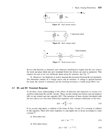
Figure 15 Real current source.
V measured, ideal
R in
Figure 16 Real voltage meter.
I in Ideal ammeter
+ V R,in –
R in
Figure 17 Real current meter.
devices that function as ammeters and voltmeters (multimeters) require that the user remove
the leads and place them into new terminals before the devices are used as ammeters. This
requires the user to be very deliberate about using the ammeter. See Fig. 17.
5. Ohmmeter. An ohmmeter is used to measure the resistance between the two terminals.
The ohmmeter consists of a voltage source and an ammeter. A voltage is applied between
the leads, the current is measured, and the resulting resistance is found using Ohm’slaw.
1.5 RL and RC Transient Response
To develop a basic understanding of the effects of inductors and capacitors in circuits, it is
useful to understand RL and RC circuits. These circuits contain one resistor and one inductor
(RL) or one resistor and one capacitor (RC). The equations of these circuits (developed with
the laws above) are first-order differential equations with constant coefficients of the form
dy
X(t) B Cy (14)
dt
If we assume step inputs, a solution of the forms in Figs. 18 and 19 is assumed as solution
to this equation. These first-order responses to step inputs rise or decay according to a time
constant T:
1. First-order rise:
y(t) Ae (1 / T )t (15)
2. First-order decay:
y(t) A(1 e (1 / T )t ) (16)