
Page 840 - Mechanical Engineers' Handbook (Volume 2)
P. 840
1 Basic Analog Electronics 831
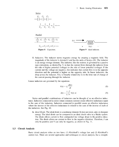
Series
C 1 C 2 C 3
1 1 1 1
= + + + •••
C C C C
E 1 2 3
Parallel
C 1 C 2 C 3
i(t)
C eq = C 1 + C 2 + C 3 + ••• + V(t) –
Figure 8 Capacitors. Figure 9 Ideal inductor.
5. Inductors. The inductor stores magnetic energy by creating a magnetic field. The
magnitude of the inductor is denoted L and has the units of henrys (H). The inductor
is an energy storage element. The inductor, like the resistor, is governed by a passive
sign convention, as shown Fig. 9, in that the current flows through the inductor from
the side of higher potential (voltage) to the side of lower potential (voltage). If the
current and the voltage are negative, this indicates that current flow is in the opposite
direction and the potential is higher on the opposite side. In linear inductors, the
drop across the inductor, V(t), is linearly related (by L) to the time rate of change of
the current passing through the inductor.
Linear inductors are governed by the equations
dI(t)
V(t) L (8)
dt
1 t
I(t) V(t) t (9)
L 0
Series and parallel combinations of inductors can be thought of as an effective induc-
tance. Inductors connected in series (share common current) create effective inductance equal
to the sum of the inductors. Inductors connected in parallel create an effective inductance
where the inverse of the effective inductance is related to the sum of the inverse of each of
the inductors. See Fig. 10.
6. Ideal Diode. The ideal diode is a nonlinear element. It does not store, add, or dissipate
energy. The ideal diode can be compared to an ideal check valve in a fluidic system.
The diode allows current to flow unimpeded (no voltage drop) in the positive direc-
tion. The diode allows no current to flow in the negative direction. Therefore, I can
only be positive and V can only be negative, as shown in Fig. 11.
1.3 Circuit Analysis
Basic circuit analysis relies on two laws: (1) Kirchhoff’s voltage law and (2) Kirchhoff’s
current law. There are several approaches and techniques to circuit analysis, but a straight-