
Page 836 - Mechanical Engineers' Handbook (Volume 2)
P. 836
1 Basic Analog Electronics 827
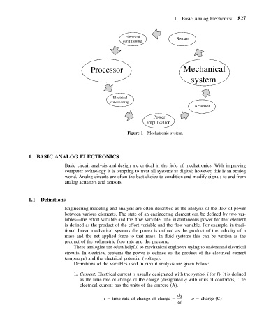
Electrical
conditioning Sensor
Processor Mechanical
system
Electrical
conditioning
Actuator
Power
amplification
Figure 1 Mechatronic system.
1 BASIC ANALOG ELECTRONICS
Basic circuit analysis and design are critical in the field of mechatronics. With improving
computer technology it is tempting to treat all systems as digital; however, this is an analog
world. Analog circuits are often the best choice to condition and modify signals to and from
analog actuators and sensors.
1.1 Definitions
Engineering modeling and analysis are often described as the analysis of the flow of power
between various elements. The state of an engineering element can be defined by two var-
iables—the effort variable and the flow variable. The instantaneous power for that element
is defined as the product of the effort variable and the flow variable. For example, in tradi-
tional linear mechanical systems the power is defined as the product of the velocity of a
mass and the net applied force to that mass. In fluid systems this can be written as the
product of the volumetric flow rate and the pressure.
These analogies are often helpful to mechanical engineers trying to understand electrical
circuits. In electrical systems the power is defined as the product of the electrical current
(amperage) and the electrical potential (voltage).
Definitions of the variables used in circuit analysis are given below:
1. Current. Electrical current is usually designated with the symbol i (or I). It is defined
as the time rate of change of the charge (designated q with units of coulombs). The
electrical current has the units of the ampere (A).
dq
i time rate of change of charge q charge (C)
dt