
Page 839 - Mechanical Engineers' Handbook (Volume 2)
P. 839
830 Mechatronics
+ V(t) –
i(t) C Figure 6 Ideal capacitor.
erned by a passive sign convention as shown in the figure in that the current flows
‘‘across’’ the capacitor from the side of higher potential (voltage) to the side of lower
potential (voltage). If the current (and the voltage) are negative, this indicates that
current flow is in the opposite direction and the potential is higher on the opposite
side. See Fig. 6. In linear capacitors, the voltage is linearly related to the time integral
of the current. Linear capacitors are governed by the equation
1 t
V(t) i(t) t (5)
C 0
or
V(t)
i(t) C (6)
t
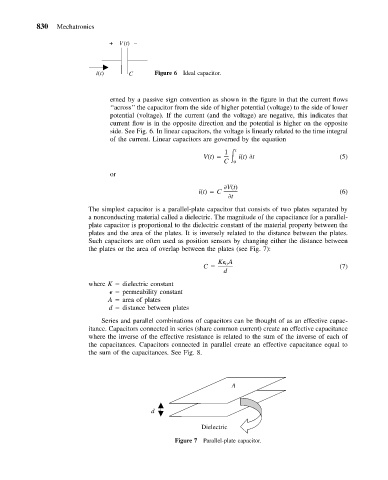
The simplest capacitor is a parallel-plate capacitor that consists of two plates separated by
a nonconducting material called a dielectric. The magnitude of the capacitance for a parallel-
plate capacitor is proportional to the dielectric constant of the material property between the
plates and the area of the plates. It is inversely related to the distance between the plates.
Such capacitors are often used as position sensors by changing either the distance between
the plates or the area of overlap between the plates (see Fig. 7):
K A
C 0 (7)
d
where K dielectric constant
permeability constant
A area of plates
d distance between plates
Series and parallel combinations of capacitors can be thought of as an effective capac-
itance. Capacitors connected in series (share common current) create an effective capacitance
where the inverse of the effective resistance is related to the sum of the inverse of each of
the capacitances. Capacitors connected in parallel create an effective capacitance equal to
the sum of the capacitances. See Fig. 8.
A
d
Dielectric
Figure 7 Parallel-plate capacitor.