
Page 141 - Mechanical Engineers' Handbook (Volume 4)
P. 141
130 Exergy Analysis, Entropy Generation Minimization, and Constructal Theory
In this expression, T(t) is the corresponding optimal temperature history of the object that
is being cooled, and C* is a constant that can be evaluated based on the time constraint, as
shown in Refs. 3 and 4. The optimal flow rate history result (˙m opt ) tells the operator that at
temperatures where U is small the flow rate should be decreased. Furthermore, because
during cooldown the gas c increases, the flow rate should decrease as the end of the process
P
nears.
In the case of energy storage by melting there is an optimal melting temperature (i.e.,
optimal type of storage material) for minimum entropy generation during storage. If T and
T are the temperatures of the heat source and the ambient, the optimal melting temperature
0
of the storage material has the value T m,opt (T T ) 1/2 .
0
7 SOLAR ENERGY CONVERSION
The generation of power and refrigeration based on energy from the sun has been the subject
of some of the oldest EGM studies, which cover a vast territory. A characteristic of these
EGM models is that they account for the irreversibility due to heat transfer in the two
temperature gaps (sun-collector and collector-ambient) and that they reveal an optimal cou-
pling between the collector and the rest of the plant.
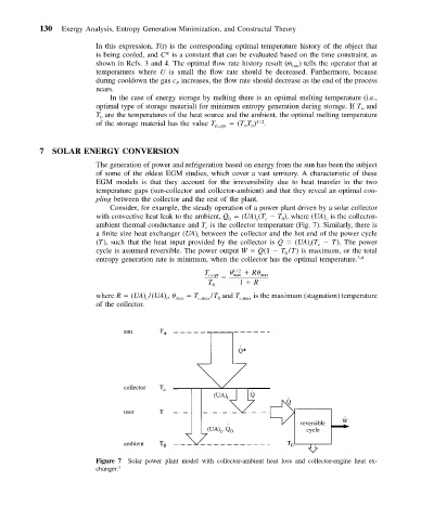
Consider, for example, the steady operation of a power plant driven by a solar collector
˙
with convective heat leak to the ambient, Q 0 (UA) (T T ), where (UA) is the collector-
c
c
0
c
ambient thermal conductance and T is the collector temperature (Fig. 7). Similarly, there is
c
a finite size heat exchanger (UA) between the collector and the hot end of the power cycle
i
˙
(T), such that the heat input provided by the collector is Q (UA) (T T). The power
c
i
˙
˙
cycle is assumed reversible. The power output W Q (1 T /T) is maximum, or the total
0
entropy generation rate is minimum, when the collector has the optimal temperature. 3,4
T c,opt 1/2 R max
max
T 0 1 R
where R (UA) /(UA) , max T c,max /T and T c,max is the maximum (stagnation) temperature
c
i
0
of the collector.
Figure 7 Solar power plant model with collector-ambient heat loss and collector-engine heat ex-
changer. 3