
Page 218 - Mechanical Engineers' Handbook (Volume 4)
P. 218
4 Boiling and Condensation Heat Transfer 207
Ah 1/2
q e,m v ƒg v
2(r )
h,w
where (r ) is the hydraulic radius of the wick structure, defined as twice the area of the
h,w
wick pore at the wick–vapor interface divided by the wetted perimeter at the wick–vapor
interface.
The boiling limit occurs when the input heat flux is so high that nucleate boiling occurs
in the wicking structure and bubbles may become trapped in the wick, blocking the liquid
return and resulting in evaporator dryout. This phenomenon, referred to as the boiling limit,
differs from the other limitations previously discussed in that it depends on the evaporator
heat flux as opposed to the axial heat flux. This expression, which is a function of the fluid
properties, can be written as
q 2 LkT 2 P
eff eff v
b,m
h ln(r /r ) r n c,m
v
i
ƒg v
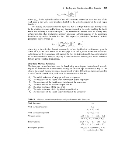
where k eff is the effective thermal conductivity of the liquid–wick combination, given in
Table 28, r is the inner radius of the heat pipe wall, and r is the nucleation site radius.
i n
After the power level associated with each of the four limitations is established, determination
of the maximum heat transport capacity is only a matter of selecting the lowest limitation
for any given operating temperature.
Heat Pipe Thermal Resistance
The heat pipe thermal resistance can be found using an analogous electrothermal network.
Figure 32 illustrates the electrothermal analog for the heat pipe illustrated in Fig. 31. As
shown, the overall thermal resistance is composed of nine different resistances arranged in
a series/parallel combination, which can be summarized as follows:
R The radial resistance of the pipe wall at the evaporator
pe
R The resistance of the liquid–wick combination at the evaporator
we
R The resistance of the liquid–vapor interface at the evaporator
ie
R The resistance of the adiabatic vapor section
ya
R The axial resistance of the pipe wall
pa
R The axial resistance of the liquid–wick combination
wa
R The resistance of the liquid–vapor interface at the condenser
ic
Table 28 Effective Thermal Conductivity for Liquid-Saturated Wick Structures
Wick Structures k eff
Wick and liquid in series kk
lw
k k (1 )
l
w
Wick and liquid in parallel k l k w (1 )
Wrapped screen k [(k k ) (1 )(k k )]
l l w l w
(k k ) (1 )(k k )]
w
l
w
l
Packed spheres k [(2k k ) 2(1 )(k k )]
w
l
w
l
l
(2k k ) (1 )(k k )
l
w
l
w
Rectangular grooves wkk
) wk (0.185wk
k l
flw l fw
f
(w w )(0.185wk
k ) l
f f