
Page 216 - Mechanical Engineers' Handbook (Volume 4)
P. 216
4 Boiling and Condensation Heat Transfer 205
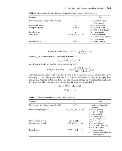
Table 26 Expressions for the Effective Capillary Radius for Several Wick Structures
Structure r c Data
Circular cylinder (artery or tunnel wick) r r radius of liquid
flow passage
Rectangular groove groove width
Triangular groove /cos groove width
half-included angle
Parallel wires wire spacing
Wire screens ( d )/2 1/2N d wire diameter
N screen mesh number
wire spacing
Packed spheres 0.41r s r s sphere radius
P
Liquid pressure drop l l Lq eff
KA h
wfg l
where L is the effective heat pipe length defined as
eff
L 0.5L L 0.5L
eff e a c
and K is the liquid permeability as shown in Table 27.
P C(ƒ Re )
Vapor pressure drop v v v v Lq eff
2
2(r ) A h
h,v
v v ƒg
Although during steady-state operation the liquid flow regime is always laminar, the vapor
flow may be either laminar or turbulent. It is therefore necessary to determine the vapor flow
regime as a function of the heat flux. This can be accomplished by evaluating the local axial
Reynolds and Mach numbers and substituting the values as shown below:
Re 2300, Ma 0.2
v
v
(ƒ Re ) 16
v
v
Table 27 Wick Permeability for Several Wick Structures
Structure K Data
2
Circular cylinder (artery or tunnel wick) r /8 r radius of liquid flow
passage
Open rectangular grooves 2 (r h,l ) /(ƒ l Re l ) /s wick porosity
2
groove width
s groove pitch
groove depth
(r h,l ) 2
/( 2
)
2
Circular annular wick 2(r h,l ) /(ƒ l Re l ) (r h,l ) r 1 r 2
2 3
Wrapped screen wick 1/122 d /(1 ) 2 d wire diameter
1 (1.05 Nd /4)
N mesh number
2 3
Packed sphere 1/37.5r s /(1 ) 2 r s sphere radius
porosity (dependent on
packing mode)