Page 351 - Mechanical Engineers' Handbook (Volume 4)
P. 351

340   Heat Pipes

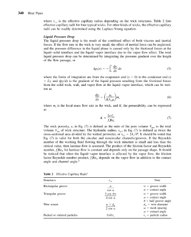
                          where r c,e  is the effective capillary radius depending on the wick structures. Table 2 lists
                          effective capillary radii for four typical wicks. For other kinds of wicks, the effective capillary
                          radii can be readily determined using the Laplace-Young equation.
                          Liquid Pressure Drop
                          The liquid pressure drop is the result of the combined effect of both viscous and inertial
                          forces. If the flow rate in the wick is very small, the effect of inertial force can be neglected,
                          and the pressure difference in the liquid phase is caused only by the frictional forces at the
                          liquid–solid interface and the liquid–vapor interface due to the vapor flow effect. The total
                          liquid pressure drop can be determined by integrating the pressure gradient over the length
                          of the flow passage, or
                                                       p (x)     x  dp l
                                                        l
                                                               0 dx  dx                        (5)
                          where the limits of integration are from the evaporator end (x   0) to the condenser end (x
                            L), and dp /dx is the gradient of the liquid pressure resulting from the frictional forces
                                    l
                          from the solid wick, wall, and vapor flow at the liquid–vapor interface, which can be writ-
                          ten as

                                                       dp l     l  ˙ m                         (6)
                                                       dx    KA     l
                                                               wl
                          where ˙m l  is the local mass flow rate in the wick, and K, the permeability, can be expressed
                          as
                                                              2	r 2
                                                          K     h,l                            (7)
                                                              ƒ Re l
                                                               l
                          The wick porosity, 	, in Eq. (7) is defined as the ratio of the pore volume V por  to the total
                          volume V tot  of wick structure. The hydraulic radius, r , in Eq. (7) is defined as twice the
                                                                     h,l
                          cross-sectional area divided by the wetted perimeter, or r h,l    2A /P. It should be noted that
                                                                            c
                          Eq. (7) is valid for both the circular and noncircular channels/grooves. If the Reynolds
                          number of the working fluid flowing through the wick structure is small and less than the
                          critical value, then laminar flow is assumed. The product of the friction factor and Reynolds
                          number, ƒ Re , for laminar flow is constant and depends only on the passage shape. It should
                                 l
                                    l
                          be noticed that when the liquid–vapor interface is affected by the vapor flow, the friction
                          factor Reynolds number product, ƒ Re , depends on the vapor flow in addition to the contact
                                                     l
                                                       l
                          angle and channel angle. 4
                          Table 2 Effective Capillary Radii 3
                          Structures                          r c,e                     Note
                          Rectangular groove                   w                  w   groove width
                                                             cos                      contact angle
                          Triangular groove                 3 cos  w              w   groove width
                                                             4 cos                    contact angle
                                                                                      half groove angle
                          Wire screen                        w   d w              d w   wire diameter
                                                             2 cos                w   mesh spacing
                                                                                      contact angle
                          Packed or sintered particles       0.41r s              r s   particle radius
   346   347   348   349   350   351   352   353   354   355   356