Page 350 - Mechanical Engineers' Handbook (Volume 4)
P. 350

3 Heat Transport Limitations  339

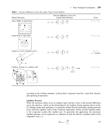
            Table 1 Pressure Differences Across the Liquid–Vapor Curved Surfaces
                                                     Pressure Difference Across the
            Names/Structures                            Liquid–Vapor Interface              Notes
                                               p v   p l
            Vapor bubble in liquid phase                 1   1     2                     r   r 1   r 2
                                                         r 1  r 2  r
                    p l
                         r
                       p v

            Liquid drop in vapor phase         p l   p v      1         2                r   r 1   r 2
                                                             1
                                                         r 1  r 2  r
                    p v
                      p l
                           r


                                                             1
            Liquid in a micro triangular groove  p v   p l                                  r 2
                                                         1

                    p v                                  r 1  r 2  r                      r   constant.
                       r
                         p l
                                               p v   p l
            Capillary wicking in a capillary tube        1   1     2     2      gh       r   r 1   r 2
              σ                                          r 1  r 2  r   r b
                 α                                                    cos
                       r
                    p v
                                    h
                      p l
                    2r b


                           according to the wicking structure, working fluid, evaporator heat flux, vapor flow channel,
                           and operating temperature.

                           Capillary Pressure
                           When the meniscus radius exists at a liquid–vapor interface, there is the pressure difference
                           across the interface, which can be determined by the Laplace-Young equation shown in Eq.
                           (2). During steady-state operation, it is generally defined that the maximum capillary pressure
                           exists when the capillary radius in the condenser approaches infinity and the capillary radius
                           in the evaporator reaches the smallest one. To generalize the application, the maximum
                           capillary pressure can be expressed as a function of only the effective capillary radius of the
                           evaporator wick, i.e.,

                                                                  2
                                                           p c,max                               (4)
                                                                  r c,e
   345   346   347   348   349   350   351   352   353   354   355