
Page 349 - Mechanical Engineers' Handbook (Volume 4)
P. 349
338 Heat Pipes
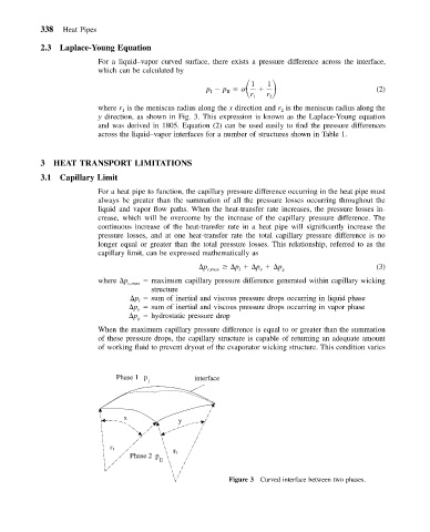
2.3 Laplace-Young Equation
For a liquid–vapor curved surface, there exists a pressure difference across the interface,
which can be calculated by
p p 1
1
I II (2)
r 1 r 2
where r is the meniscus radius along the x direction and r is the meniscus radius along the
2
1
y direction, as shown in Fig. 3. This expression is known as the Laplace-Young equation
and was derived in 1805. Equation (2) can be used easily to find the pressure differences
across the liquid–vapor interfaces for a number of structures shown in Table 1.
3 HEAT TRANSPORT LIMITATIONS
3.1 Capillary Limit
For a heat pipe to function, the capillary pressure difference occurring in the heat pipe must
always be greater than the summation of all the pressure losses occurring throughout the
liquid and vapor flow paths. When the heat-transfer rate increases, the pressure losses in-
crease, which will be overcome by the increase of the capillary pressure difference. The
continuous increase of the heat-transfer rate in a heat pipe will significantly increase the
pressure losses, and at one heat-transfer rate the total capillary pressure difference is no
longer equal or greater than the total pressure losses. This relationship, referred to as the
capillary limit, can be expressed mathematically as
p c,max p p p g (3)
l
v
where p c,max maximum capillary pressure difference generated within capillary wicking
structure
p sum of inertial and viscous pressure drops occurring in liquid phase
l
p sum of inertial and viscous pressure drops occurring in vapor phase
v
p hydrostatic pressure drop
g
When the maximum capillary pressure difference is equal to or greater than the summation
of these pressure drops, the capillary structure is capable of returning an adequate amount
of working fluid to prevent dryout of the evaporator wicking structure. This condition varies
Phase 1 p interface
I
x y
r 1
r 2
Phase 2 p
II
Figure 3 Curved interface between two phases.