
Page 462 - Mechanical Engineers' Handbook (Volume 4)
P. 462
7 System Components 451
7.2 Condensers
The refrigerant condenser is used to reject the heat energy added to the refrigerant during
compression and the heat energy absorbed in the evaporator. This heat energy is typically
rejected to either water or air.
The amount of heat energy added to the refrigerant during compression depends on the
compressor power and can become a significant part of the condenser load for low-
temperature systems. Common types of water-cooled condensers include shell-and-tube,
18
shell-and-coil, tube-in-tube, and brazed-plate. Shell-and-coil condensers are smaller in size
(3.5–50 kW) and circulate the cooling water through coiled tubes inside an external shell.
The refrigerant condenses on the outside of the coiled tubes. Tube-in-tube condensers can
be found in sizes up to 175 kW and consist of tubes within larger tubes. The refrigerant is
condensed either in the annular space between the tubes or inside the inner tube. Brazed-
plate condensers can be found in sizes up to 350 kW and are constructed of plates brazed
together to form separate channels. 18
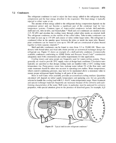
Shell-and-tube condensers can be found in sizes from 3.5 to 35,000 kW. These con-
densers with finned tubes and fixed tube sheets provide an economical exchanger design for
refrigerant use. Figure 13 shows an example of a shell-and-tube condenser. Commercially
available condensers conforming to ASME Boiler and Pressure Vessel Code 21 construction
adequately meet both construction and safety requirements for this application.
Cooling towers and spray ponds are frequently used for water-cooling systems. These
generally are sized to provide 29 C supply water at design load conditions. Circulation rates
typically are specified so that design cooling loads are handled with a 5.6 C cooling-water
temperature rise. Pump power, tower fans, makeup water (about 3% of the flow rate), and
water treatment should be taken into account in operating-cost studies. Water temperatures,
which control condensing pressure, may have to be maintained above a minimum value to
ensure proper refrigerant liquid feeding to all parts of the system.
River or well water, when available, provides an economical cooling medium. Quantities
circulated will depend on initial supply temperatures and pumping cost, but are generally
selected to handle the cooling load with 8.3–16.6 C water-temperature range. Water treatment
and special exchanger materials frequently are necessary because of the corrosive and scale-
forming characteristics of the water. Well water, in particular, must be analyzed for corrosive
properties, with special attention given to the presence of dissolved gases, for example, H S
2
Figure 13 Typical shell-in-tube refrigerant condenser. 3