Page 471 - Mechanical Engineers' Handbook (Volume 4)
P. 471
460   Refrigeration


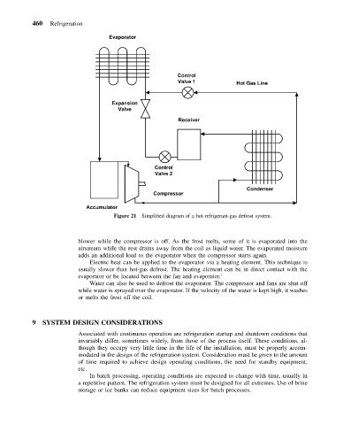
                                     Figure 21 Simplified diagram of a hot-refrigerant-gas defrost system.


                          blower while the compressor is off. As the frost melts, some of it is evaporated into the
                          airstream while the rest drains away from the coil as liquid water. The evaporated moisture
                          adds an additional load to the evaporator when the compressor starts again.
                             Electric heat can be applied to the evaporator via a heating element. This technique is
                          usually slower than hot-gas defrost. The heating element can be in direct contact with the
                          evaporator or be located between the fan and evaporator. 1
                             Water can also be used to defrost the evaporator. The compressor and fans are shut off
                          while water is sprayed over the evaporator. If the velocity of the water is kept high, it washes
                          or melts the frost off the coil.


           9  SYSTEM DESIGN CONSIDERATIONS
                          Associated with continuous operation are refrigeration startup and shutdown conditions that
                          invariably differ, sometimes widely, from those of the process itself. These conditions, al-
                          though they occupy very little time in the life of the installation, must be properly accom-
                          modated in the design of the refrigeration system. Consideration must be given to the amount
                          of time required to achieve design operating conditions, the need for standby equipment,
                          etc.
                             In batch processing, operating conditions are expected to change with time, usually in
                          a repetitive pattern. The refrigeration system must be designed for all extremes. Use of brine
                          storage or ice banks can reduce equipment sizes for batch processes.

