
Page 469 - Mechanical Engineers' Handbook (Volume 4)
P. 469
458 Refrigeration
Figure 19 Typical temperature and pressure distribution in a capillary tube. (Reprinted by permission
from 2002 ASHRAE Handbook of Refrigeration. American Society of Heating, Refrigerating, and Air-
Conditioning Engineers, Inc., www.ashrae.org.)
amount of refrigerant charge than systems using TXVs or EEVs. Design charts for capillary
tubes can be found in Ref. 1 for R-12 and R-22.
Short-Tube Restrictor
Short-tube restrictors are applied in many systems that formerly used capillary tubes. Figure
20 illustrates a short-tube restrictor and its housing. The restrictors are inexpensive, reliable,
and easy to replace. In addition, for systems such as heat pumps, which reverse cycle, short-
tube restrictors eliminate the need for a check valve. Short-tubes vary in length from 10 to
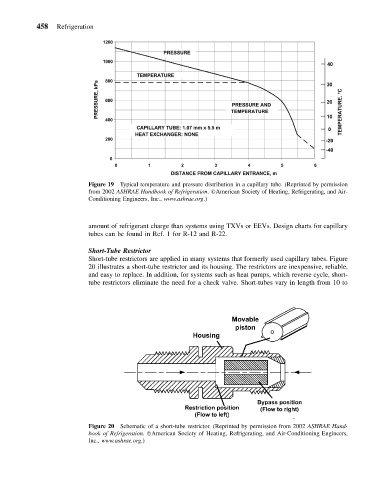
Figure 20 Schematic of a short-tube restrictor. (Reprinted by permission from 2002 ASHRAE Hand-
book of Refrigeration. American Society of Heating, Refrigerating, and Air-Conditioning Engineers,
Inc., www.ashrae.org.)