Page 561 - Mechanical Engineers' Handbook (Volume 4)
P. 561
550   Indoor Environmental Control

                          transferred to zone i from other zones, i   j; m source  is the mass (rate) generated by the
                          source in zone i; q source  is the thermal energy generated by the sources in zone i; m sink  is the
                          mass removed from the zone, and q sink  is the thermal energy removed from zone i.
                             Flow paths (elements) connect zones and allow airflow in one or both directions. The
                          flow between different zones is usually driven by a pressure and/or temperature difference,
                          so the wind data and outdoor temperatures can be used to estimate infiltration flow rates.
                             Multizone models have benefits and drawbacks. A major benefit of multizone models
                          is that they can quickly calculate the airflow, heat flux, or contaminant transportation between
                          different zones (rooms) in an entire building. Furthermore, specifying building zones is rel-
                          atively simple because boundary conditions such as walls, windows, and supply/exhaust do
                          not require detailed specifications. The simplicity of multizone models, on the other hand,
                          does not allow them to provide detailed information on the airflow pattern, velocity, tem-
                          perature, and concentration distributions in individual rooms (zones). However, more com-
                          plicated programs based on computational fluid dynamics (CFD) are capable of predicting
                          all those distributions with accuracy.
                             CFD programs numerically solve a set of partial differential equations for the conser-
                          vation of mass, momentum (Navier-Stokes equations), energy, and species concentration.
                          There are three groups of numerical methods for solving the equations: control volume, finite
                          element, and spectral methods. The control volume method is widely used in CFD for build-
                          ing environment simulations. This CFD model divides a single room into fine control vol-
                          umes, order(s) of magnitude smaller than the building zones. Typically, a control volume
                                                            3
                          would be anywhere between 1 and 10 cm . In each control volume, a uniform density,
                          temperature, velocity, and species concentration is assumed. Also, each control volume has
                          to satisfy mass (in the form of the continuity equation), momentum, energy, and species
                          conservation. The major difference between the multizone and CFD models is the additional
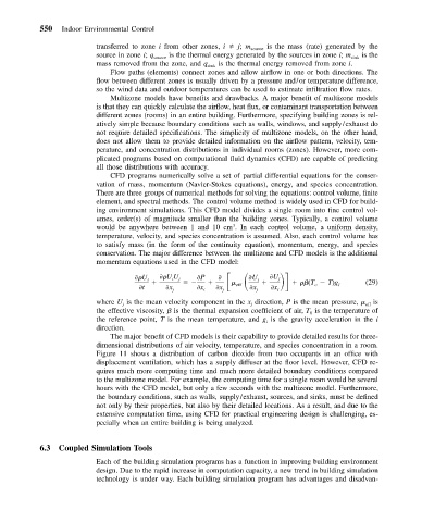
                          momentum equations used in the CFD model:

                                                                       U
                                            UU      P

                                     U i     i  j                U i    j
                                                                                (T   T)g      (29)
                                     t      x       x    x   eff   x   x         o     i
                                             j       i    j       j     i
                          where U is the mean velocity component in the x direction, P is the mean pressure,   eff  is
                                j
                                                                 j
                          the effective viscosity,   is the thermal expansion coefficient of air, T is the temperature of
                                                                                0
                          the reference point, T is the mean temperature, and g is the gravity acceleration in the i
                                                                     i
                          direction.
                             The major benefit of CFD models is their capability to provide detailed results for three-
                          dimensional distributions of air velocity, temperature, and species concentration in a room.
                          Figure 11 shows a distribution of carbon dioxide from two occupants in an office with
                          displacement ventilation, which has a supply diffuser at the floor level. However, CFD re-
                          quires much more computing time and much more detailed boundary conditions compared
                          to the multizone model. For example, the computing time for a single room would be several
                          hours with the CFD model, but only a few seconds with the multizone model. Furthermore,
                          the boundary conditions, such as walls, supply/exhaust, sources, and sinks, must be defined
                          not only by their properties, but also by their detailed locations. As a result, and due to the
                          extensive computation time, using CFD for practical engineering design is challenging, es-
                          pecially when an entire building is being analyzed.
           6.3  Coupled Simulation Tools
                          Each of the building simulation programs has a function in improving building environment
                          design. Due to the rapid increase in computation capacity, a new trend in building simulation
                          technology is under way. Each building simulation program has advantages and disadvan-

