
Page 220 - Mechanics Analysis Composite Materials
P. 220
Chapter 4. Mechanics of a composite layer 205
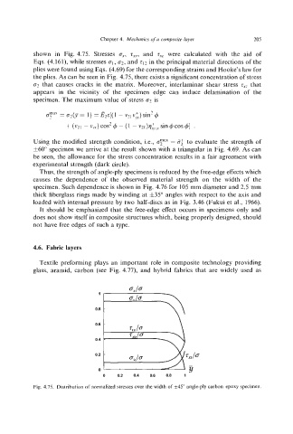
shown in Fig. 4.75. Stresses e,, z.~~,and z,, were calculated with the aid of
Eqs. (4.161), while stresses el,c2,and in the principal material directions of the
plies were found using Eqs. (4.69) for the corresponding strains and Hooke's law for
the plies. As can be seen in Fig. 4.75, there exists a significant concentration of stress
e' that causes cracks in the matrix. Moreover, interlaminar shear stress z,~ that
appears in the vicinity of the specimen edge can induce delamination of the
specimen. The maximum value of stress e? is
Using the modified strength condition, i.e., cy = 8; to evaluate the strength of
f60" specimen we arrive at the result shown with a triangular in Fig. 4.69. As can
be seen, the allowance for the stress concentration results in a fair agreement with
experimental strength (dark circle).
Thus, the strength of angle-ply specimensis reduced by the free-edge effects which
causes the dependence of the observed material strength on the width of the
specimen. Such dependence is shown in Fig. 4.76 for 105 mm diameter and 2.5 mm
thick fiberglass rings made by winding at f35" angles with respect to the axis and
loaded with internal pressure by two half-discs as in Fig. 3.46 (Fukui et al., 1966).
It should be emphasized that the free-edge effect occurs in specimens only and
does not show itself in composite structures which, being properly designed, should
not have free edges of such a type.
4.6. Fabric layers
Textile preforming plays an important role in composite technology providing
glass, aramid, carbon (see Fig. 4.77), and hybrid fabrics that are widely used as
\'
0.6
0.4
0.2
0
0 0.2 0.4 0.6 0.8 1
Fig. 4.75. Distribution of normalized stresses over the width of f45"angle-ply carbon-epoxy specimen.