
Page 230 - Mechanics Analysis Composite Materials
P. 230
Chapter 4. Mechanics of a composite layer 215
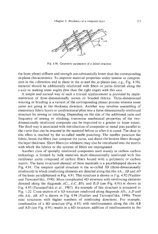
Fig. 4.90. Geometric parameters of a lattice structure.
the layer plane) stiffness and strength are substantiaIly lower than the corresponding
in-plane characteristics. To improve material properties under tension or compres-
sion in the z-direction and in shear in the xz-and the p-planes (see, e.g., Fig. 4.18),
material should be additionally reinforced with fibers or yarns directed along the
z-axis or making some angles (less than the right angle) with this axis.
A simple and natural way of such a triaxial reinforcement is provided by imple-
mentation of three-dimensionally woven or braided fabrics. Three-dimensional
weaving or braiding is a variant of the corresponding planar process wherein some
yarns are going in the thickness direction. Another way involves assembling of
elementary fabric layers or unidirectional plies into a three-dimensionally reinforced
structure by sewing or stitching. Depending on the size of the additional yarn and
frequency of sewing or stitching, transverse mechanical properties of the two-
dimensionally reinforced composite can be improved to a greater or lesser extent.
The third way is associated with introduction of composite or metal pins parallel to
the z-axis that can be inserted in the material before or after it is cured. The close to
this effect is reached by the so-called needle punching. The needles puncture the
fabric, break the fibers that compose the yarns, and direct the broken fibers through
the layer thickness. Short fibers (or whiskers) may also be introduced into the matrix
with which the fabrics or the systems of fibers are impregnated.
Another class of spatially reinforced composites used mainly in carbon-carbon
technology is formed by bulk materials multi-dimensionally reinforced with fine
rectilinear yarns composed of carbon fibers bound with a polymeric or carbon
matrix. The basic structural element of these materials is a parallelepiped shown in
Fig. 4.91. The simplest spatial structure is the so-called 3D (three-dimensionally
reinforced) in which reinforcing elements are directed along the ribs AAI,AB and AD
of the basic parallelepiped in Fig. 4.9 1. This structure is shown in Fig. 4.92 (Vasiliev
and Tarnopol’skii, 1990). More complicated 4D structure with reinforcing elements
directed along the diagonals ACI,AIC,BDI and BID (see Fig. 4.91) is shown in
Fig. 4.93 (Tarnopol’skii et al., 1987). An example of this structure is presented in
Fig. 1.22. Cross-section of a 5D structure reinforced along diagonals AD1 ,A IDand
ribs AAI,AB, AD is shown in Fig. 4.94 (Vasiliev and Tarnopol’skii, 1990). There
exist structures with higher numbers of reinforcing directions. For example,
combination of a 4D structure (Fig. 4.93) with reinforcements along the ribs AB
and AD (see Fig. 4.91) results in a 6D structure; addition of reinforcements in the