
Page 232 - Mechanics Analysis Composite Materials
P. 232
Chapter 4. Mechanics of a composite layer 217
Fig. 4.94. Cross-section of a 5D spatially reinforced structure.
et al. (1992). However, for practical applications these characteristics are usually
obtained by experimental methods. Being orthotropic in the global coordinates of
the structure x, y, z, spatially reinforced composites are described within the
framework of a phenomenological model ignoring their microctructure by three-
dimensional constitutive equations analogous to Eqs. (4.53) or Eqs. (4.54) in which
1 should be changed for x, 2 - for y, and 3 - for z. These equations include nine
independent elastic constants. Stiffness coefficients in the basic plane, i.e.,
E,, E,, G,,, and vxr, are determined using traditional tests developed for unidirec-
tional and fabric composites and discussed in Sections 3.4, 4.2, and 4.6. Transverse
modulus E, and the corresponding Poisson’s ratios v, and vy can be found studying
material compression in the z-direction. Transverse shear moduli G,.. and Gy can be
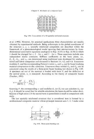
calculated using the results of a three-point beam bending test shown in Fig. 4.95.
A specimen cut out of the material is loaded with force P, and the deflection at
the central point, w,is measured. According to the theory of composite beams
(Vasiliev, 1993)
Knowing P, the corresponding w and modulus E, (or E,) we can calculate G,, (or
Cy).It should be noted that for reliable calculation the beam should be rather short,
because of high ratios l/h the second term in parenthesis is small in comparison with
unity.
The last spatially reinforced structure that is considered here is formed by a
unidirectional composite material whose principal material axes 1, 2, 3 make some
tZ I P
Fig. 4.95. Three-point bending test.