
Page 314 - Mechanics Analysis Composite Materials
P. 314
Chapter 6. Failure criteria and strength of laminates 299
where A,,,,, are specified by Eqs. (6.49) and (6.50), and hl = 0.62 mm, h? = 0.6 mm
are the thicknesses of the helical and circumferential layers. Using again Eqs. (6.48)
we get for p 2 p!?:
0‘1” = 137.7p, o:’) = 122.7~
.
The cylinder failure can now be caused by the fracture of either helical fibers or
circumferential fibers. The corresponding values of the ultimate pressure can be
found from the following equations:
o!’) = 83.9~::) + 92.l(pf’ -pi’)) + 137.7(p, -pf)) = 0;.
o!?) = 112p!’) + 134.6(pL2) -p!’)) + 122.7(pU -p!?)) = 0; ,
where p!’) = 1.1 MPa and pf’ = 1.4 MPa.
The first of these equations yields pu = 10 MPa, while the second - pu =
10.7 MPa.
Thus, the failure of the structure under study occurs at p, = 10 MPa as a result of
fiber fracture in the helical layer.
Dependencies of strains that can be calculated using Eqs. (6.47) and the
appropriate values of B,,,,, are shown in Fig. 6.22 (solid lines). As can be seen, the
Table 6.1
Burst pressure for filament wound fiberglass pressure vessels
Diameter of Layer Calculated burst Number of Experimental
the vessel thickness (mm) pressure (MPa) tested vessels burst pressure
(mm)
11 I h 1 Mean value Variation
(MPa) coeflicient (YO)
200 0.62 0.60 10 5 9.9 6.8
200 0.92 0.93 15 5 13.9 3.3
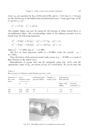
Fig. 6.23. The failure mode of a composite pressure vessel.