
Page 384 - Mechanics Analysis Composite Materials
P. 384
Chapter 8. Optimal composite structures 369
i.e., each layer with angle +4i should be accompanied with the layer of the same
thickness but with angle -4i.
Consider, for example, the uniform tension such that iVr = N,. = N, N,. = 0,
n, = 1, n,. = 0, A = 0.5. For this case, Eqs. (8.12) and (8.13) yield
(8.15)
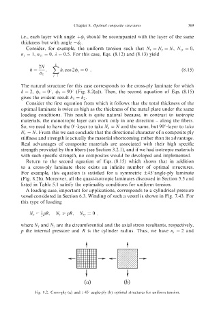
The natural structure for this case corresponds to the cross-ply laminate for which
k = 2, 4, = 0", 42 = 90" (Fig. 8.2(a)). Then, the second equation of Eqs. (8.15)
gives the evident result hl = 62.
Consider the first equation from which it follows that the total thickness of the
optimal laminate is twice as high as the thickness of the metal plate under the same
loading conditions. This result is quite natural because, in contrast to isotropic
materials, the monotropic layer can work only in one direction - along the fibers.
So, we need to have the 0"-layer to take N, = N and the same, but 90"-layer to take
N,, = N. From this we can conclude that the directional character of a composite ply
stiffness and strength is actually the material shortcoming rather than its advantage.
Real advantages of composite materials are associated with their high specific
strength provided by thin fibers (see Section 3.2. l), and if we had isotropic materials
with such specific strength, no composites would be developed and implemented.
Return to the second equation of Eqs. (8.15) which shows that in addition
to a cross-ply laminate there exists an infinite number of optimal structures.
For example, this equation is satisfied for a symmetric f45"angle-ply laminate
(Fig. 8.2b). Moreover, all the quasi-isotropic laminates discussed in Section 5.5 and
listed in Table 5.1 satisfy the optimality conditions for uniform tension.
A loading case, important for applications, corresponds to a cylindrical pressure
vessel considered in Section 6.3. Winding of such a vessel is shown in Fig. 7.43. For
this type of loading
where N, and N,, are the circumferential and the axial stress resultants, respectively,
p the internal pressure and R is the cylinder radius. Thus, we have n,, = 2 and
Fig. 8.2. Cross-ply (a) and f45" angle-ply (b) optimal structures for uniform tension.