
Page 386 - Mechanics Analysis Composite Materials
P. 386
Chapter 8. Optimal composite structures 37 1
As a rule, helical plies are combined with circumferential plies as in Fig. 7.43. For
this case, k = 3, hl = hl = h4/2, = -& = 4, h3 = h90, c$3 = 90°, and Eq. (8.17)
gives
(8.18)
Because the thickness cannot be negative, this equation is valid for 0 6 4 6 40.For
Q 4 6 90", the helical layer should be combined with the axial one, i.e., we
should put k = 3, hl = hZ = hd/2, 4, = = 4 and h3 = ho, 43= 0". Then
(8.19)
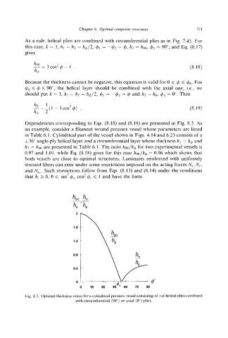
Dependencies corresponding to Eqs. (8.18) and (8.19) are presented in Fig. 8.3. As
an example, consider a filament wound pressure vessel whose parameters are listed
in Table 6.1. Cylindricalpart of the vessel shown in Figs. 4.14 and 6.23 consists of a
f36" angle-ply helical layer and a circumferentiallayer whose thickness hl = hb and
hZ = h90 are presented in Table 6.1. The ratio hyo/h&for two experimental vessels is
0.97 and 1.01, while Eq. (8.18) gives for this case hyo/h&= 0.96 which shows that
both vcsscls are close to optimal structures. Laminates reinforced with uniformly
stressed fibers can exist under some restrictions imposed on the acting forces Ify,F,.,
and iVyy.Such restrictions follow from Eqs. (8.13) and (8.14) under the conditions
that hi 2 0, 0 6 sin' 4i,cos' 4i6 1 and have the form
2
1.6
1.2
0.8
0.4
0
Fig. 8.3. Optimal thickness ratios for a cylindrical pressure vessel consisting of i$helical plies combined
with circumferential (90") or axial (0") plies.