
Page 80 - Mechanics Analysis Composite Materials
P. 80
Chapter 3. Mechanics of a unidirectional ply 65
f
Fig. 3.13. Tension of a bundle of fibers.
IS,GPa
0 0.5 1 1.5 2 2.5 3
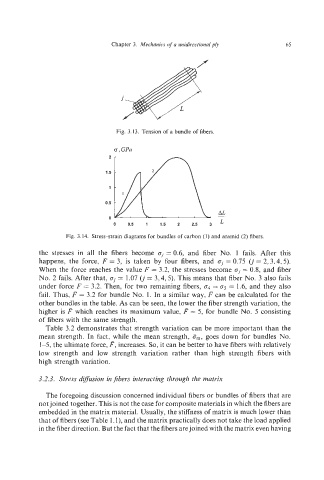
Fig. 3.14. Stress-strain diagrams for bundles of carbon (I) and aramid (2) fibers.
the stresses in all the fibers become oj= 0.6, and fiber No. 1 fails. After this
happens, the force, F = 3, is taken by four fibers, and oj = 0.75 (j = 2,3,4,5).
When the force reaches the value F = 3.2, the stresses become oj= 0.8, and fiber
No. 2 fails. After that, oj= 1.07 0’= 3,4,5). This means that fiber No. 3 also fails
under force F = 3.2. Then, for two remaining fibers, 04 = o5 = 1.6, and they also
fail. Thus, F = 3.2 for bundle No. 1. In a similar way, F can be calculated for the
other bundles in the table. As can be seen, the lower the fiber strength variation, the
higher is F which reaches its maximum value, F = 5, for bundle No. 5 consisting
of fibers with the same strength.
Table 3.2 demonstrates that strength variation can be more important than the
mean strength. In fact, while the mean strength, Sm,goes down for bundles No.
1-5, the ultimate force, P, increases. So, it can be better to have fibers with relatively
low strength and low strength variation rather than high strength fibers with
high strength variation.
3.2.3. Stress dijrusion in fibers interacting through the matrix
The foregoing discussion concerned individual fibers or bundles of fibers that are
not joined together. This is not the case for composite materials in which the fibers are
embedded in the matrix material. Usually, the stiffness of matrix is much lower than
that of fibers (see Table 1. l), and the matrix practically does not take the load applied
in the fiber direction. But the fact that the fibers arejoined with the matrix even having