
Page 101 - Mechanics of Asphalt Microstructure and Micromechanics
P. 101
94 Ch a p t e r Th r e e
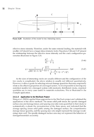
FIGURE 3.24 Illustration of the model for two interacting cracks.
effective stress intensity. Therefore, under the same external loading, the material with
smaller l/d should have a larger stress intensity factor. Equations 3-46 and 3-47 present
the relationship between the effective stress intensity and the crack configuration pa-
rameters illustrated in Figure 3.24.
K eff 1
1 = (3-46)
K 0 1− q
1
q = 1 ∫ 1 1 + t ( 1 − 11)dt (3-47)
2(/δη + / )λ η −1 1 − t δ 2 2 2
−
1 − () /( tC /η )
η
As the sizes of interacting cracks are usually different and the configuration of the
two cracks is complicated, the above relation is usually not followed quantitatively.
However, it offers a guide for selecting rational damage quantities that may empirically
relate to the effective properties of a damaged system. As it is impossible to develop any
analytical models for a damaged system with randomly distributed cracks, empirical
quantities are in many cases useful in materials evaluations. This is illustrated in the
example application.
3.6.1.4 Application to the WesTrack Project
Wang et al. (2001b) applied these approaches to the WesTrack project and validated the
applications of the above methods. The mean solid path tensor, the specific damaged
surface area and damage tensor, and spacing-size ratio were quantified in their study to
systematically evaluate the microstructure of the three mixes, and indicated that the
average spacing (mean solid path) among the damaged surface, the comprehensive
damage tensor quantity, and the spacing size ratio might represent the damage (weak-
ening) state well. The specific damaged surface area may not represent the behavior of
damaged materials accurately.