
Page 107 - Mechanics of Asphalt Microstructure and Micromechanics
P. 107
100 Ch a p t e r F o u r
non-invasive. For most invasive techniques, measurements tend to be limited to only a
few points to minimize interference and cost. To obtain accurate displacement mea-
surements, testers using invasive techniques must make sure that the sensors deform
compatibly with the material being measured so that the interference of the sensors
with the material being tested is minimized. For non-invasive measurements, there are
no such limitations and thus techniques such as imaging offer the potential for non-
invasive strain measurement of bonded granular materials such as AC and cement
concrete. Non-invasive measurements have been widely applied in medical science
(IAEA, 1995), in fluid flow measurement (Hanssan et al., 1991), and in granular particle
tracking (Warr, 1994). These methods are presented first for the two-dimensional (2D)
case using optical imaging and are then extended to the three-dimensional (3D) case
using XCT imaging. A digital image correlation method, mainly applicable to the 2D
case, will be discussed in the last section of this chapter.
4.2 2D Methodology
This section presents a method that permits non-invasive evaluation of the strains in
the mastic using optical imaging of particle positions. It will be directly illustrated for
specimens tested in the GLWT, while the methodology is equally applicable for use
with other testing systems and specimens.
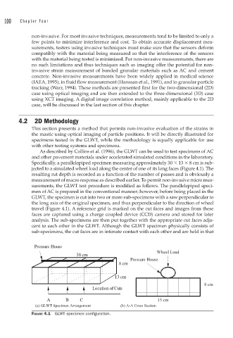
As described by Collins et al. (1996), the GLWT can be used to test specimens of AC
and other pavement materials under accelerated simulated conditions in the laboratory.
Specifically, a parallelepiped specimen measuring approximately 30 13 8 cm is sub-
jected to a simulated wheel load along the center of one of its long faces (Figure 4.1). The
resulting rut depth is recorded as a function of the number of passes and is obviously a
measurement of macro response as described earlier. To permit non-invasive micro mea-
surements, the GLWT test procedure is modified as follows. The parallelepiped speci-
men of AC is prepared in the conventional manner; however, before being placed in the
GLWT, the specimen is cut into two or more sub-specimens with a saw perpendicular to
the long axis of the original specimen, and thus perpendicular to the direction of wheel
travel (Figure 4.1). A reference grid is marked on the cut faces and images from these
faces are captured using a charge coupled device (CCD) camera and stored for later
analysis. The sub-specimens are then put together with the appropriate cut faces adja-
cent to each other in the GLWT. Although the GLWT specimen physically consists of
sub-specimens, the cut faces are in intimate contact with each other and are held in that
Pressure House
Wheel Load
30 cm
Pressure House
8 cm
13 cm
8 cm
Location of Cuts
A B C 13 cm
(a) GLWT Specimen Arrangement (b) A-A Cross Section
FIGURE 4.1 GLWT specimen confi guration.