
Page 108 - Mechanics of Asphalt Microstructure and Micromechanics
P. 108
Experimental Methods to Characterize the Heterogeneous Strain F ield 101
position by the clamping system of the GLWT. In this manner, the cut faces, although
available for optical imaging at various stages during the rutting process, are located
within the center of the specimen during actual application of the load by the rutting
wheel, and thus are isolated from any boundary effects associated with the test system.
The remainder of the rutting test procedure is implemented as with normal specimens.
When the desired number of passes of the simulated rutting wheel has been ap-
plied, the macro-response of the specimen is determined using the conventional proce-
dures described by Collins et al. (1996) and Kandhal and Cooley (2003). The specimen
is then separated into the sub-specimens to enable additional images to be captured
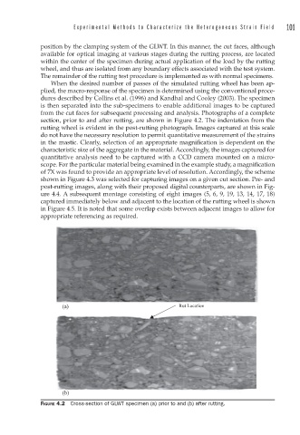
from the cut faces for subsequent processing and analysis. Photographs of a complete
section, prior to and after rutting, are shown in Figure 4.2. The indentation from the
rutting wheel is evident in the post-rutting photograph. Images captured at this scale
do not have the necessary resolution to permit quantitative measurement of the strains
in the mastic. Clearly, selection of an appropriate magnification is dependent on the
characteristic size of the aggregate in the material. Accordingly, the images captured for
quantitative analysis need to be captured with a CCD camera mounted on a micro-
scope. For the particular material being examined in the example study, a magnification
of 7X was found to provide an appropriate level of resolution. Accordingly, the scheme
shown in Figure 4.3 was selected for capturing images on a given cut section. Pre- and
post-rutting images, along with their proposed digital counterparts, are shown in Fig-
ure 4.4. A subsequent montage consisting of eight images (5, 6, 9, 19, 13, 14, 17, 18)
captured immediately below and adjacent to the location of the rutting wheel is shown
in Figure 4.5. It is noted that some overlap exists between adjacent images to allow for
appropriate referencing as required.
(a) Rut Location
(b)
FIGURE 4.2 Cross-section of GLWT specimen (a) prior to and (b) after rutting.