
Page 213 - Mechanics of Asphalt Microstructure and Micromechanics
P. 213
Fundamentals of Phenomenological Models 205
6.6.5 Modified Griffith Equation
The Griffith criterion is applicable to brittle fracture. Irwin (1948) and Orowan (1948)
modified the Griffith criterion to include the energy (g s ) required to produce plastic flow:
1
⎛ 2 E( γ + γ ⎞ ) 2
σ = ⎜ s p ⎟ (6-202)
f ⎝ πa ⎠
6.6.5.1 Energy Release Rate
Griffith also proved that the energy release rate for the elliptic crack is equal to:
d∏ πσ 2 a
G =− = (6-203)
dA E
The above sections present a general philosophy to link the external stress that will
cause crack opening and fracture to the crack size, surface energy, and energy required
to produce plastic deformation. It offers an assessment approach of materials in terms
of fracture failure. Nevertheless, AC is full of inherent defects of different sizes and
shapes. It is difficult to directly use such criteria in AC.
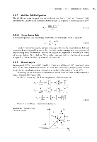
6.6.6 Stress Analysis
Westergaard (1939), Irwin (1957), Sneddon (1946), and Williams (1957) developed solu-
tions for the stress distributions around the crack tips. For 2D cases, the stress state around
the tip (polar coordinate system with origin at the tip) is illustrated in Figure 6.15.
Depending on the directions of the external forces, there are three modes of fractur-
ing as illustrated in Figure 6.16.
For Mode I fracturing, the three components of the stresses are:
K ⎛ θ ⎞ ⎡ ⎛ θ ⎞ ⎛ 3 θ ⎞ ⎤
σ = I cos ⎜ ⎟ ⎢ 1 − sin ⎜ ⎟ sin ⎜ ⎟ ⎥
xx ⎝ 2 ⎠ ⎠
2 πr ⎝ ⎠ 2 ⎣ ⎝ ⎠ 2 ⎦
K ⎛ θ ⎞ ⎡ ⎛ θ ⎞ ⎛ 3 θ ⎞ ⎤
σ = I cos ⎜ ⎟ ⎢ 1 + sin ⎜ ⎟ sin ⎜ ⎟ ⎥
yy ⎝ 2 ⎠ ⎠
2 πr ⎝ ⎠ 2 ⎣ ⎝ ⎠ 2 ⎦
K ⎛ θ ⎞ ⎛ θ ⎞ ⎛ 3 θ ⎞
τ = I cos ⎜ ⎟ sin ⎜ ⎟ cos ⎜ ⎟
xy 2 πr ⎝ ⎠ 2 ⎝ ⎠ 2 ⎝ 2 ⎠
(6-204)
Where K I is the Mode I stress intensity factor.
FIGURE 6.15 Stress around yy
the tip of a crack. Y
τ xy
xx
xx
r yx
crack yy
X