
Page 83 - Mechanics of Asphalt Microstructure and Micromechanics
P. 83
76 Ch a p t e r Th r e e
3.4.2.2 3D Quantification Methods
To accurately quantify the distribution of the contact normal and branch vector distri-
butions, it is necessary to determine the boundary coordinates of the particle. Wang, et
al. (2004) developed a method to reconstruct the 3D microstructure of granular materi-
als using tomography imaging and image analysis. This method can be used to obtain
the surface coordinates of each individual particle in a particulate system. A brief de-
scription of the method is presented below. The study by Wang et al. (2003) mainly fo-
cused on the methodology development, which directly used a real aggregate. The de-
scription of the method is directly tied into an application as an example. The aggregate
is Louisiana sandstone passing a 12.5 mm sieve size but retained on 9.5 mm sieve size.
The aggregate was placed in a 35 mm film cartridge for X-ray scanning. The size of the
cross-section images was 512 512 pixels with a resolution of 0.07 mm/pixel. The in-
terval of the cross-sections was 0.42 mm or 6.0 pixels. Using the method by Wang, et al.
(2003), the particle cross-sections belonging to the same particle were identified and
reconstructed into the 3D particle representation. The x, y, and z coordinates for 72
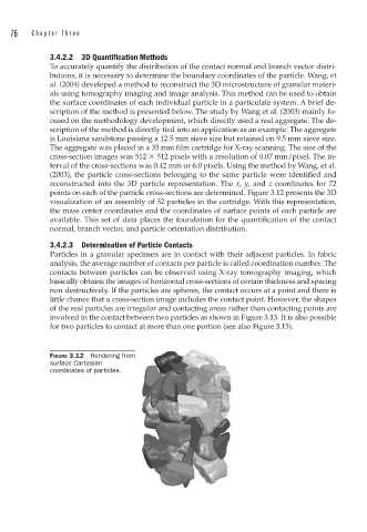
points on each of the particle cross-sections are determined. Figure 3.12 presents the 3D
visualization of an assembly of 52 particles in the cartridge. With this representation,
the mass center coordinates and the coordinates of surface points of each particle are
available. This set of data places the foundation for the quantification of the contact
normal, branch vector, and particle orientation distribution.
3.4.2.3 Determination of Particle Contacts
Particles in a granular specimen are in contact with their adjacent particles. In fabric
analysis, the average number of contacts per particle is called coordination number. The
contacts between particles can be observed using X-ray tomography imaging, which
basically obtains the images of horizontal cross-sections of certain thickness and spacing
non-destructively. If the particles are spheres, the contact occurs at a point and there is
little chance that a cross-section image includes the contact point. However, the shapes
of the real particles are irregular and contacting areas rather than contacting points are
involved in the contact between two particles as shown in Figure 3.13. It is also possible
for two particles to contact at more than one portion (see also Figure 3.13).
FIGURE 3.12 Rendering from
surface Cartesian
coordinates of particles.