
Page 238 - Mechanics of Microelectromechanical Systems
P. 238
4. Microtransduction: actuation and sensing 225
Application of an electric field can modify the distances between dipoles and
arrange them adequately in a poled configuration. However, over the Curie
point, the crystalline structure is cubic and symmetric with no dipoles as the
negative and positive poles do coincide. As a consequence, poling cannot be
applied and therefore the piezoelectric effect cannot be produced over this
critical point.
The two principles, the direct and the reversed piezoelectric effects, can
be utilized for transduction purposes in both macro-scale and micro-scale
applications, and Fig. 4.41 gives a sketch of both phenomena. Application of
the external compressive forces F in Fig 4.41 (a) will compress the poled
piezoelectric material by a quantity which, in turn, will generate a field
(g stands for generated) and the corresponding current in an external
electric circuit. The direction of the generated field in this case opposes the
mechanical action, as it tries to restore the piezoelectric material to its initial
dimensions. The reverse piezoelectric effect is shown in Fig. 4.41 (b).
Application of an external field (m stands for motor) in opposition to the
poling field will generate an expansion of the piezoelectric sample by a
quantity Both examples also show that the direct and reversed
piezoelectric effects are directional, in terms of both electrical field and
mechanical deformation.
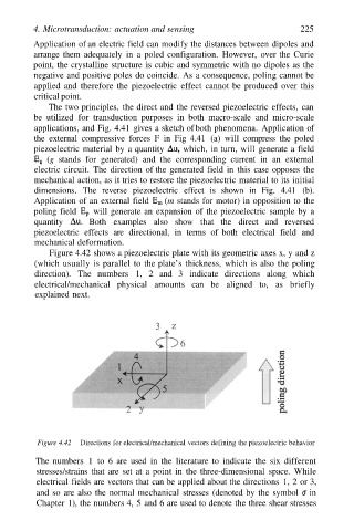
Figure 4.42 shows a piezoelectric plate with its geometric axes x, y and z
(which usually is parallel to the plate’s thickness, which is also the poling
direction). The numbers 1, 2 and 3 indicate directions along which
electrical/mechanical physical amounts can be aligned to, as briefly
explained next.
Figure 4.42 Directions for electrical/mechanical vectors defining the piezoelectric behavior
The numbers 1 to 6 are used in the literature to indicate the six different
stresses/strains that are set at a point in the three-dimensional space. While
electrical fields are vectors that can be applied about the directions 1, 2 or 3,
and so are also the normal mechanical stresses (denoted by the symbol in
Chapter 1), the numbers 4, 5 and 6 are used to denote the three shear stresses