
Page 294 - Mechatronics for Safety, Security and Dependability in a New Era
P. 294
Ch56-I044963.fm Page 278 Thursday, July 27, 2006 8:22 AM
Ch56-I044963.fm
278
278 Page 278 Thursday, July 27, 2006 8:22 AM
This paper is organized as follows: in chapter 1 an introduction to the topic is given. Chapter 2
describes the prototype manufacturing process, the use of robot system is described in chapter 3.
Results from actual tests are in chapter 4. Finally conclusions are given in chapter 5.
2. DESCRIPTION OF THE PROCESS
The principle of the short series production is explained as follows. The geometry of the casting
will be machined into the sand. After machining and coating the mould, the work piece will be cast.
Depending on the properties of the casting, this process is repeated until a piece with sufficient
qualifications has been achieved. This may require one to ten iteration steps. Numerous castings
that are produced in small batches, including prototypes and spare parts, they will be produced by
substitution of the pattern making process with advanced robotics and utilization of a digital library
created from a CAD model, thus economizing in terms of materials and storage space used and time
spent. Moreover, patterns will be manufactured by using the same system by only substituting sand
mould with plastic material. This will increase end user's productivity over 50% and decrease costs
substantially, especially when prototypes are developed. From a technical point of view, new
products, of enhanced shapes will be created in extremely short times and in as many items as
desired. Finally, the milling and mould making can be totally isolated from the foundry
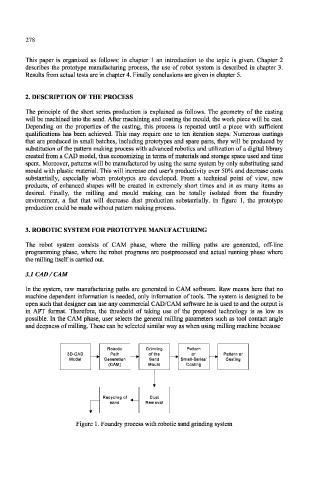
environment, a fact that will decrease dust production substantially. In figure 1, the prototype
production could be made without pattern making process.
3. ROBOTIC SYSTEM FOR PROTOTYPE MANUFACTURING
The robot system consists of CAM phase, where the milling paths are generated, off-line
programming phase, where the robot programs are postprocessed and actual running phase where
the milling itself is carried out.
3.1 CAD /CAM
In the system, raw manufacturing paths are generated in CAM software. Raw means here that no
machine dependent information is needed, only information of tools. The system is designed to be
open such that designer can use any commercial CAD/CAM software he is used to and the output is
in APT format. Therefore, the threshold of taking use of the proposed technology is as low as
possible. In the CAM phase, user selects the general milling parameters such as tool contact angle
and deepness of milling. These can be selected similar way as when using milling machine because
Robotic Grinding
3D-CAD Path of the Pattern or
Model Generation Sand Small-Series' Casting
(CAM) Mould Casting
Recycling of Dust
sand Removal
Figure 1. Foundry process with robotic sand grinding system