
Page 289 - Mechatronics for Safety, Security and Dependability in a New Era
P. 289
Ch55-I044963.fm Page 273 Tuesday, August 1, 2006 9:39 PM
Tuesday, August
Page 273
9:39 PM
1, 2006
Ch55-I044963.fm
273
273
Furthermore, it is expected that reading some particular RFIDs instead of entering some infor-
mation manually, such as operator name, physical location of the work-cell, and others. So, the
tracking system can judge whether given identifier represents some WIP or process equipment.
3.3 Allocation
In this implementation, we use simple algorithm described in the Section 2 to allocate demand
to corresponding WIP. The basic data, which are the typical durations from one gate to the next
or previous gate and the bills of materials, are given and stored in the shared data space among
multiple processing agents, described later. The typical durations for due date deduction may
differ from those for calculating estimated times for following gates. Both durations are defined
for all product types, but the users can define other values to override them for respective types.
We named the lists of same type WIPs, arranged in the order of expected time passing a predefined
gate, as "preceding list." In other hand, we named the list of same type demand, arranged in the
order of due time at a predefined gate, as "priority list." Their priority is defined only by the due
time order, and we ignore any other aspects.demands.
All demands and WIPs are processed in building material type by type, and in the case of the
material type made from multiple parts, the demands of those parts is newly created at the gate
at which those parts are assembled together, according to the bills of materials. The due time of
the parts are given from the due time of the assembled WIP at the same gate. The estimated time
of a WIP to pass the assembling gate is calculated as the latest one of those times of its parts.
3.4 User Interface
In this subsection, we describe the user interface screens implemented. The user interface of this
system was developed as the application of WWW (World Wide Web) system, in order to make
them accessible from not only desk-top computer systems but also portable data terminals.
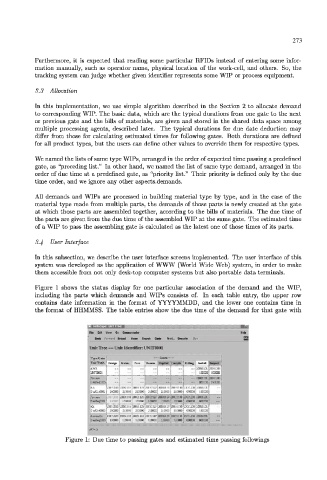
Figure 1 shows the status display for one particular association of the demand and the WIP,
including the parts which demands and WIPs consists of. In each table entry, the upper row
contains date information in the format of YYYYMMDD, and the lower one contains time in
the format of HHMMSS. The table entries show the due time of the demand for that gate with
•-I
Hie Edit View Go Communeator H'lp |
T Back ard Reload Hime Search Guide Pr Hi... Ss.ril, s
4
UnitTr ee — Unit Identifier: UNITOOO1
---Gates -
1 Design Proc. | Assem. Sk^Ort •'"•• r •' -. •; Install Imaged
gy
IJNITODOl 150000: 180000
...
i-
- |
_ _ _ _ _ _ ... ..."I. ^ ' x ^ ! x " .
IAA [20031030 20031115 20:31123 ....."„ _ _ _ _ _
11 210000 210000 21000: i 210000 i 210000 21:000 i osoooo 150000 i
20031130 ; 20031201 2
; 30031110 3:0:31123" c : , , • - ; • ; ; : , •» -»»; -
1 : 120000 12000:| ,=cooo; mm,
— • •
[20031030 20031115 20:31123 0031127[20031123[20031130 [2003:201120 0 3 1 2 0 1 ] ~
JOmUrrtOOQ. [ 210000 210000 ;iooo: 21000QJ 2100Q0 21:000 ! 050000 lSOOOOj
120031025 20031109 50:31122 0031127 20031129
^ ^ 3 120000 120000 12000:| 120000 12
IF7-U
Figure 1: Due time to passing gates and estimated time passing followings