
Page 315 - Mechatronics for Safety, Security and Dependability in a New Era
P. 315
Ch60-I044963.fm Page 299 Thursday, July 27, 2006 9:00 AM
Thursday, July 27, 2006
Page 299
9:00 AM
Ch60-I044963.fm
299
299
Hydraulic DSP
Controller DSP
Controller DSP Hydraulic DSP
Wait for data until packet received or 2 ms passed
t\ Wait for data until packet received or 2 ms passed ^ Wait 2 ms since last sampling
Wait 2 ms since last sampling
2
2 ms
Packet
I™ Packet Send control to valve
Send control to valve
Sample position
Increase differentiation time by 2 ms or signal Sample position
Increase differentiation time by 2 ms o signal
“
dSPACE packet lost"
dSPACE “packet lost ” Send position to controller
Send position to controller
Wait 1.8 ms for control data
1.8 ms for control data
Wait
Calculate controller output or send position to
Calculate controller output or send pos tion to ^
dSPACE and get control data in respon
dSPACE and get control data in response Packet received?
Packet received?
No
Send control data to hydraulics unit •— No Yes
Send control data to hydraulics unit
Reset differentiation time to 2 ms
Reset differentiation time to 2 ms 10 last packets lost? No Use previous
10 last packets lost?
Use previou
control value
control value
Yes
Use value 0 to close the valve
Use value 0 to close the valve
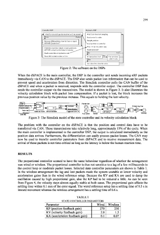
Figure 2: The software on the DSPs
When the dSPACE is the main controller, the DSP in the controller unit sends incoming nRF packets
immediately via CAN to the dSPACE. The DSP also sends packet loss information that can be used to
prevent speed and acceleration from distortion. The Simulink controller polls the CAN buffer of the
dSPACE and when a packet is received, responds with the controller output. The controller DSP then
sends the controller output via the transceivers. The model is shown in Figure 3. It also illustrates the
velocity calculation block with packet loss compensation. If a packet is lost, the block increases the
previous position value by the previous increase. This equals to holding the last velocity.
Figure 3: The Simulink model of the state controller and its velocity calculation block
The problem with the controller on the dSPACE is that the position and control data have to be
transferred via CAN. These transmissions take relatively long, approximately 15% of the cycle. When
the main controller is implemented in the controller DSP, the output is calculated immediately as the
position data arrives. Furthermore, the differentiation can easily process packet losses. The CAN may
now be used to transfer controller parameters from dSPACE and to receive measurement data. The
arrival of these packets is not time-critical as long as the latency is below the human reaction time.
RESULTS
The proportional controller seemed to have the same behaviour regardless of whether the arrangement
was wired or wireless. The proportional controller is thus not sensitive to a lag of a few milliseconds in
the control loop or moderate packet losses. Selected state controller parameters are shown in Table 1.
In the wireless arrangement the lag and lost packets made the system unstable at lower velocity and
acceleration gains than in the wired reference setup. Because the KV and KA are used to damp the
oscillation caused by high proportional gain, also the KP had to be reduced a little. As can be seen
from Figure 4, the velocity stays almost equally stable at both cases. The proportional gain affects the
settling time within 0.1 mm of the error signal. The wired reference setup has a settling time of 0.3 s in
inward movement whereas the wireless arrangement has a settling time of 0.6 s.
TABLE 1
STATE CONTROLLER PARAMETERS
Parameter Wired Wireless
KP (position feedback gain) 270 230
KV (velocity feedback gain) 2.0 1.5
KA (acceleration feedback gain) 0.1 0.07