Page 373 - Mechatronics for Safety, Security and Dependability in a New Era
P. 373

Ch72-I044963.fm  Page 357  Tuesday, August 1, 2006  9:53 PM
                      Page 357
                                      1, 2006
                                           9:53 PM
                            Tuesday, August
            Ch72-I044963.fm
                                                                                          357
                                                                                          357
                                 Constant a
                                 Constant a
                                                                      Constant b
                     12                                  0.25
                     1                                   0.20
                     a
                     e 8                                 b

                     u  l                                e  u  0.15
                     V 6                                 l  a
                     a
                     4                                   V  0.10
                     2                                   0.05
                     0                                   0.00
                                      2.0
                                  1.5
                      0.  0.  1.0  1.5  2.0  2.5  3.0  3.5  0.0       1.5        3.0  3.5
                                          2.5
                                                                             2.5
                                                                          2.0
                                  Current, A                   0.  1.0  1.5  2.0  2.5  3.0
                                  Current, A
                                                                       Current , A
                                                                       Current, A
                                     (a)                                 (b)
                                     (a)
                                                                         (b)
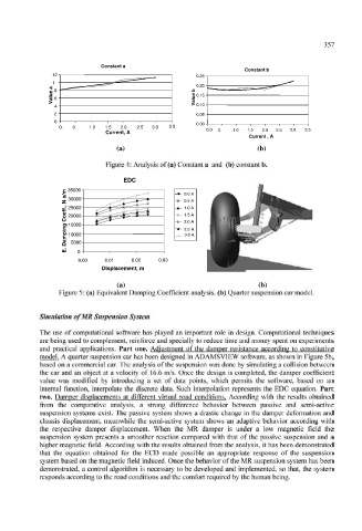
                                  Figure 4: Analysis of (a) Constant a  and  (b) constant b.
                                       EDC
                                          EDC
                        m  35000
                                                      0.0 A
                        /                             0.0 A
                        s
                        N 30000                     -»- 0.5 A
                                                      0.5 A

                        ,
                        f 25000                     -4 - 1.0  A
                                                      1.0 A
                        .
                        f
                        e                           -X- 1.5A
                                                      1.5 A
                        C 20000
                        o
                                                      2.0 A
                                                    -* - 2.0 A
                        n 15000
                        g
                                                      2.5 A
                        i                           - « - 2.5  A
                        p                             3.0 A
                        m 10000                     -+"  3.0A
                        a  5000
                        D

                        .
                        E  0


                                                0.03
                           0.00   0.01   0.02   0.03
                           0.00
                                         0.02
                                  0.01
                                 Displacement, m
                                 Displacement, m
                                                                         (b)
                                     (a)
                                     (a)                                 (b)
                      Figure 5: (a) Equivalent Damping Coefficient  analysis, (b) Quarter suspension car model.
                  Simulation of MR Suspension System
                  The  use  of  computational  software  has played  an  important  role  in  design.  Computational  techniques
                  are being used to complement, reinforce  and specially to reduce time and money  spent on experiments
                  and  practical  applications.  Part  one.  Adjustment  of  the  damper  resistance  according  to  constitutive
                  model. A quarter suspension car has been designed  in ADAMSVIEW  software,  as shown in Figure 5b,
                  based  on a commercial car. The analysis of the suspension was done by simulating a collision between
                  the  car  and  an  object  at  a velocity  of  16.6 m/s. Once the  design  is completed,  the  damper  coefficient
                  value  was  modified  by  introducing  a  set  of  data  points,  which  permits  the  software,  based  on  an
                  internal  function,  interpolate  the  discrete  data.  Such  interpolation  represents  the  EDC  equation.  Part
                  two.  Damper  displacements  at  different  virtual  road  conditions. According  with  the  results  obtained
                  from  the  comparative  analysis,  a  strong  difference  behavior  between  passive  and  semi-active
                  suspension  systems  exist.  The  passive  system  shows a drastic  change  in the  damper  deformation  and
                  chassis  displacement,  meanwhile  the  semi-active  system  shows  an  adaptive  behavior  according  with
                  the  respective  damper  displacement.  When  the  MR  damper  is  under  a  low  magnetic  field  the
                  suspension  system presents  a  smoother  reaction  compared  with  that  of  the passive  suspension  and  a
                  higher magnetic field. According with the results obtained  from  the analysis,  it has been  demonstrated
                  that  the  equation  obtained  for  the  ECD  made  possible  an  appropriate  response  of  the  suspension
                  system based on the magnetic  field  induced. Once the behavior of the MR suspension  system has been
                  demonstrated,  a control  algorithm  is necessary  to  be developed  and  implemented,  so that,  the  system
                  responds according to the road conditions and the comfort required  by the human being.
   368   369   370   371   372   373   374   375   376   377   378