
Page 371 - Mechatronics for Safety, Security and Dependability in a New Era
P. 371
Ch72-I044963.fm Page 355 Tuesday, August 1, 2006 9:53 PM
Page 355
Tuesday, August 1, 2006
9:53 PM
Ch72-I044963.fm
355
355
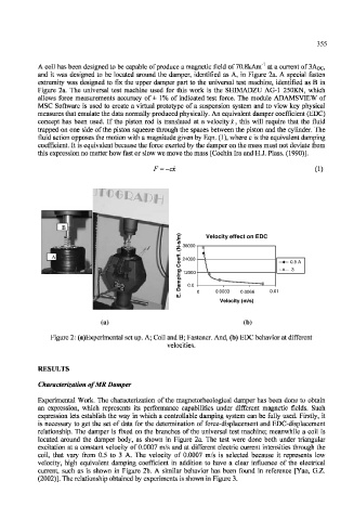
A coil has been designed to be capable of produce a magnetic field of 70.8kAm"' at a current of 3ADC,
and it was designed to be located around the damper, identified as A, in Figure 2a. A special fasten
extremity was designed to fix the upper damper part to the universal test machine, identified as B in
Figure 2a. The universal test machine used for this work is the SH1MADZU AG-1 250KN, which
allows force measurements accuracy of ± 1% of indicated test force. The module ADAMS VIEW of
MSC Software is used to create a virtual prototype of a suspension system and to view key physical
measures that emulate the data normally produced physically. An equivalent damper coefficient (EDC)
concept has been used. If the piston rod is translated at a velocity x, this will require that the fluid
trapped on one side of the piston squeeze through the spaces between the piston and the cylinder. The
fluid action opposes the motion with a magnitude given by Eqn. (1), where c is the equivalent damping
coefficient. It is equivalent because the force exerted by the damper on the mass must not deviate from
this expression no matter how fast or slow we move the mass [Cochin Ira and H.J. Plass. (1990)].
F = -ex (1)
B
) Velocity effect on EDC
m Velocity effect on EDC
/
s
36000
. - 36000
N
(
•
.
A f f
e
24000
o > 24000 —000.5A
0.5 A
C O \
g 12000 -•— 3 3
i 12000
n
p
m a. ^ -
0.0
a 0.0
D 0.0033 0.0066 0.01
0.01
0 0.0033 0.0066
.
E
Velocity (m/s)
Velocity (m/s)
(b)
(a) (b)
(a)
Figure 2: (a)Experimental set up. A; Coil and B; Fastener. And, (b) EDC behavior at different
velocities.
RESULTS
Characterization of MR Damper
Experimental Work. The characterization of the magnetorheological damper has been done to obtain
an expression, which represents its performance capabilities under different magnetic fields. Such
expression lets establish the way in which a controllable damping system can be fully used. Firstly, it
is necessary to get the set of data for the determination of force-displacement and EDC-displacement
relationship. The damper is fixed on the branches of the universal test machine; meanwhile a coil is
located around the damper body, as shown in Figure 2a. The test were done both under triangular
excitation at a constant velocity of 0.0007 m/s and at different electric current intensities through the
coil, that vary from 0.5 to 3 A. The velocity of 0.0007 m/s is selected because it represents low
velocity, high equivalent damping coefficient in addition to have a clear influence of the electrical
current, such as is shown in Figure 2b. A similar behavior has been found in reference [Yao, G.Z.
(2002)]. The relationship obtained by experiments is shown in Figure 3.