
Page 366 - Mechatronics for Safety, Security and Dependability in a New Era
P. 366
Ch71-I044963.fm Page 350 Tuesday, August 1, 2006 4:45 PM
Ch71-I044963.fm
350
350 Page 350 Tuesday, August 1, 2006 4:45 PM
EXPERIMENTAL RESULTS
For the Kalman filter a linear state-space model of the mechanical system is derived. The friction and
other nonlinearities are assumed to be system noise, which the Kalman filter handles as a random
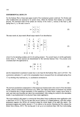
process. The estimated states of the system are velocity of the motor vi, velocity of the load V2, and
spring force F s, i.e. the state vector is:
v l
x 2 = V, (3)
X, F s
The state matrix A, input matrix B and output matrix C are described as:
b b 1 - j -
02, 02, —
b b 1
,B = 0
m 2 m /W, (4)
0
k -k 0
C = [l 0 0]
where b is the damping constant, and k is the spring constant. The control input u is in this application
motor thrust F e. These matrices are discretisized for the real-time Kalman filter. The process noise
covariance Q in this application is:
100 0 0
Q = 0 10 0 (5)
0 0 1
and the measurement covariance is scalar due to one input for the Kalman filter, and it is /?=0.01. The
acceleration estimation x 2 used in the compensation loop is measured from the estimated spring force
F s by dividing it by load mass 022, i.e. acceleration estimation is:
(6)
02,
The derived acceleration compensation is first tested and implemented in the control of the simulation
model, which is introduced in (Hirvonen et al., 2004). The whole simulation environment was carried
out in Simulink due to simple mechanics. In the modelling of a linear motor, a space vector theory is
used, and main non-linearities are taken into consideration. After testing the control in the simulation
model, it was implemented in the physical linear motor application.
The motor studied in this paper is a commercial three-phase linear synchronous motor application with
a rated force of 675 N. The moving part (the mover) consists of a slotted armature, while the surface
permanent magnets (the SPMs) are mounted along the whole length of the path (the stator). The
permanent magnets are slightly skewed (1.7°) in relation to the normal. Skewing the PMs reduces the
detent force (Gieras, 2001). The moving part is set up on an aluminum base with four recirculating