
Page 367 - Mechatronics for Safety, Security and Dependability in a New Era
P. 367
Ch71-I044963.fm Page 351 Tuesday, August 1, 2006 4:45 PM
1, 2006
Page 351
4:45 PM
Tuesday, August
Ch71-I044963.fm
351
351
roller bearing blocks on steel rails. The position of the linear motor was measured using an optical
linear encoder with a resolution of approximately one micrometer.
A spring-mass mechanism was built on a tool base in order to act as a flexible tool (for example, a
picker that increases the level of excitation). The mechanism consists of a moving mass, which can be
altered in order to change the natural frequency of the mechanism and a break spring, which is
connected to the moving mass on the guide. The mechanism's natural frequency was calculated at
being 9.1 Hz for a mass of 4 kg.
The physical linear motor application was driven in such a way that the proposed velocity controller
was implemented in Simulink to gain the desired force reference. The derived algorithm was
transferred to C code for dSPACE's digital signal processor (DSP) to use in real-time. The force
command, F*, was fed into the drive of the linear motor using a DS1103 I/O card. The computational
time step for the velocity controller was 1 ms, while the current controller cycle was 31.25 ixs.
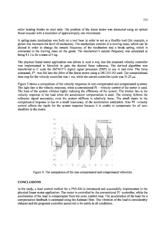
Figure 3 shows a comparison of the velocity responses in non-compensated and compensated systems.
The light line is the velocity response, when a conventional PI - velocity control of the motor is used.
The load of the system vibrates highly reducing the efficiency of the system. The thicker line is the
velocity response of the load when the acceleration compensation is used. The velocity follows the
reference signal accurately; even the system stiffness is relatively loose. The small ripple in the
compensated response is due to a small inaccuracy of the acceleration estimation. Also PT -velocity
control affects the ripple for the system response because it is unable to compensate for all non-
idealities in the motor.
Figure 3: The comparison of the non-compensated and compensated velocities.
CONCLUSIONS
In the study, a load control method for a PMLSM is introduced and successfully implemented in the
physical linear motor application. The motor is controlled by the conventional PI -controller, while the
acceleration of the load is compensated from the outer control loop. The acceleration of the load for a
compensation feedback is estimated using the Kalman Filter. The vibration of the load is considerably
reduced and the proposed controller perceived to be stable in all conditions.