
Page 41 - Mechatronics for Safety, Security and Dependability in a New Era
P. 41
Ch06-I044963.fm Page 25 Tuesday, July 25, 2006 11:50 AM
Tuesday, July 25,2006
Page 25
Ch06-I044963.fm
11:50 AM
25 25
!„->!„+1 ,
XYZ:worl d coordinat e sys .
x'y'z':ro d coordinat e sys .
xyz:gyr o coordinat e sys .
a) (b )
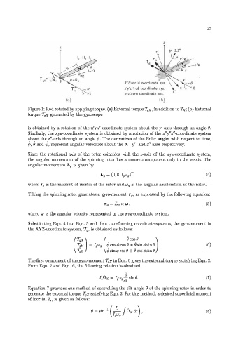
Figure 1: Rod rotated by applying torque, (a) External torque T gX. in addition to T x: (b) External
torque T gX generated by the gyroscope
is obtained by a rotation of the x'y'z'-coordinate system about the y'-axis through an angle 0.
Similarly, the xyz-coordinate system is obtained by a rotation of the x"y"z"-coordinate system
about the z"-axis through an angle •(/>. The derivatives of the Euler angles with respect to time.
4>. 6 and -ip, represent angular velocities about the X-, y'- and z"-axes respectively.
Since the rotational axis of the rotor coincides with the z-axis of the xyz-coordinate system.
the angular momentum of the spinning rotor has a nonzero component only in the z-axis. The
angular momentum L g is given by
Lg = (0, 0, IgUJgf (4)
where /,, is the moment of inertia of the rotor and 6j g is the angular acceleration of the rotor.
Tilting the spinning rotor generates a gyro-moment r 9 , as expressed by the following equation:
Tg = LgX LJ. (5)
where OJ is the angular velocity represented in the xyz-coordinate system.
Substituting Eqn. 4 into Eqn. 5 and then transforming coordinate systems, the gyro-moment in
the XYZ-coordinate system, T lp is obtained as follows:
'T gX\ I
T gY = IgUjg 6 cos 6 cos 6 + 6 sin 6 sin 6 (6)
y Tgz j \d> sin <p cos 6 + 9 cos 6 sin 6 /
The first component of the gyro-moment T gX in Eqn. 6 gives the external torque satisfying Eqn. 2.
From Eqn. 2 and Eqn. 6, the following relation is obtained:
(7)
Equation 7 provides one method of controlling the tilt angle 6 of the spinning rotor in order to
generate the external torque T gx satisfying Eqn. 2. For this method, a desired superficial moment
of inertia, /,, is given as follows:
(8)