
Page 448 - Mechatronics for Safety, Security and Dependability in a New Era
P. 448
Ch87-I044963.fm Page 432 Monday, August 7, 2006 11:32 AM
Ch87-I044963.fm
432
432 Page 432 Monday, August 7,2006 11:32 AM
' ..Stttr-workspace ? Sob-workspace 7') Sui
p
A whole required workspace
:../
Adjust
Active rolary jvinl
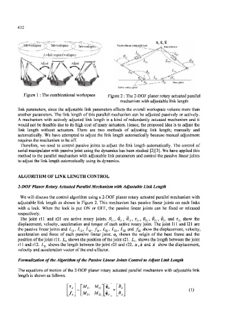
Figure 1 : The combinational workspace Figure 2 : The 2-DOF planer rotaiy actuated parallel
mechanism with adjustable link length
link parameters, since the adjustable link parameters effects the overall workspace volume more than
another parameters. The link length of this parallel mechanism can be adjusted passively or actively.
A mechanism with actively adjusted link length is a kind of redundantly actuated mechanism and it
would not be feasible due to its high cost of many actuators. Hence, the proposed idea is to adjust the
link length without actuators. There are two methods of adjusting link length; manually and
automatically. We have attempted to adjust the link length automatically because manual adjustment
requires the mechanism to be off.
Therefore, we need to control passive joints to adjust the link length automatically. The control of
serial manipulator with passive joint using the dynamics has been studied [2][3]. We have applied this
method to the parallel mechanism with adjustable link parameters and control the passive linear joints
to adjust the link length automatically using its dynamics.
ALGORITHM OF LINK LENGTH CONTROL
2-DOF Planer Rotary Actuated Parallel Mechanism with Adjustable Link Length
We will discuss the control algorithm using a 2-DOF planer rotary actuated parallel mechanism with
adjustable link length as shown in Figure 2. This mechanism has passive linear joints on each links
with a lock. When the lock is put ON or OFF, the passive linear joints can be fixed or released
respectively.
The joint rll and r21 are active rotary joints. 0 U , 0 U , 6> M , r M , 6> 2I , & 21, 6> 2I and r 2l show the
displacement, velocity, acceleration and torque of each active rotary joint. The joint 111 and 121 are
the passive linear joints and L u, L u, L n, f u, L 22, L 22, L 22 and f 22 show the displacement, velocity,
acceleration and force of each passive linear joint. o 0 shows the origin of the base frame and the
r
position of the joint ll. L o shows the position of the joint r21. L u shows the length between the joint
rl 1 and rl2. L 2l shows the length between the joint r21 and r22. x, x and x show the displacement,
velocity and acceleration vector of the end-effector.
Formulization of the Algorithm of the Passive Linear Joints Control to Adjust Link Length
The equations of motion of the 2-DOF planer rotary actuated parallel mechanism with adjustable link
length is shown as follows.
(1)
M , , My