
Page 450 - Mechatronics for Safety, Security and Dependability in a New Era
P. 450
Ch87-I044963.fm Page 434 Monday, August 7, 2006 11:32 AM
Ch87-I044963.fm
434
434 Page 434 Monday, August 7,2006 11:32 AM
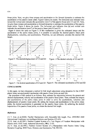
linear joints. Next, we give these torques and acceleration to the forward dynamics to estimate the
acceleration of the passive linear joints. Figure 6 shows its results. The horizontal axis indicates time
2
[s] and the vertical axis indicates the acceleration [cm/s ] of the passive linear joint 112 and 122. Next,
we give these torques and acceleration to forward dynamics to estimate the acceleration of the passive
linear joints. Figure 6 shows its results. The horizontal axis indicates time [s] and vertical axis
indicates the acceleration [cm/s ] of the passive linear joint 112 and 122.
Figure 6 shows the same as Figure 5. If this mechanism is given the estimated torque and the
acceleration of the active rotary joints, it is possible to calculate the desired passive linear joint
displacements, velocities, and accelerations. Therefore, we can ultimately calculate the desired link
length.
I * ~!t
£ US I \ / \
1 *
% K I / \
^ :?i \
§ H r. \ h \
/
I « | « \ " S / / \
1 \ \
. US
SO 1011
Time [s]
Figure 3 : The desired displacement of 112 and 122 Figure : 4 The desired velocity of 112 and 122
I too - | (00 s
U
N 409 - r i 4O0 4 400 M 411)
H
Z -*) -
i ' C 0 0
-:»
™
•S -4(10 1 8 4tO
1
= - M • 600 ' -100 (Ml _
ii
SO 100 SB Kill it 1M 51 IN
Time Is] Time [s] Time Is] lime [s]
Figure 5 : The desired acceleration of 112 and 122 Figure 6 : The estimated acceleration of 112 and 122
CONCLUSIONS
In this paper, we have discussed a method for link length adjustment using dynamics for the 2-DOF
planer rotary actuated parallel mechanism with passive linear joints on each link.
The procedure of this method is as follows: first, estimate the trajectories between the present and
desired displacement, velocity and acceleration of the passive linear joints. Then, estimate the torques
and accelerations of the active rotary joints in order to solve the accelerations, velocities and
displacements of passive linear joints. By setting the torques and accelerations to the active rotary
joints, the desired acceleration is generated on the passive linear joints. By achieving the desired
trajectories of the passive linear joints, we obtain the desired link length.
References
[1] T. Arai, et al.(2000). Parallel Mechanisms with Adjustable link length. Proc. IEEE/RSJ 2000
International Conference on Intelligent Robotics and Systems, 61 \-616.
[2] H. Arai, et al.(1991). Position Control System of a Two Degree of Freedom Manipulator with
Passive Joint. IEEE Trans. Industrial Electronics, 38:1, 15-20.
[3] H. Arai, et al.(1991). Position Control System of a Manipulator with Passive Joints Using
Dynamic Coupling. IEEE Trans. Robotics and Automation, 7:4, 528-534.