
Page 94 - Mechatronics for Safety, Security and Dependability in a New Era
P. 94
Ch17-I044963.fm Page 78 Monday, August 7, 2006 12:42 PM
Ch17-I044963.fm
78 78 Page 78 Monday, August 7, 2006 12:42 PM
TOWEL SPREADING SYSTEM
Figure 1 shows a scene in towel spreading. In this research, two robot arms, a Js2 from Kawasaki
Heavy Industries with 6 D.O.F and an RCH-40 from Yamaha with 5 D.O.F, both equipped with
grippers that were designed to manipulate clothes are used. The grippers have force sensors to detect
the force being applied to the fabric and also 4 infrared sensors each in order to detect whether or not
the fabric is inside the gripper. Figure 2 shows the details of the gripper. The grippers were designed so
that they can stand up to 400gf of force and at the same time being sensitive to force change. The gap
between the two fingers of a gripper (written as gap of a gripper later on) is controlled using encoder of
a motor shown. A CCD camera is also used to detect the corner(s) of the towel and is fix positioned in
front the two robot arms as shown in Figurel. The images taken by the CCD camera are in 8-bit gray
scale and 640x480 dots in size. An image processing board TRV-CPW5 is also equipped.
Infrared LEDs
Ball screw Infrared LEDs
Strain gage
0.7 mm
Phototransistors
Spur gear
6 m 1m
• CCD camera Motor with rotary encoder
Motor with rotary encoder
62 mm
Figure 1: Clothes spreading system Figure 2: Gripper designed for clothes spreading
FINDING & GRASPING OF THE FIRST CORNER
In this chapter, we will explain to you our proposed method on how to detect and hold the first corner
of a rectangular towel using simple image processing method. After the towel is picked up randomly
and being held in the air, the lowest point to the ground is usually one of the four corners of the towel.
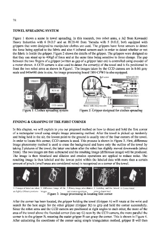
In order to locate this corner, CCD camera is used. This process is shown in Figure 3. First, difference
image photometry method is used to erase the background and leave only the outline of the towel by
taking 2 pictures of the towel, the latter one taken after the robot has slightly moved downwards (about
5mm). The two images are then subtracted and the resulting image (difference image) will be produced.
The image is then binarized and dilation and erosion operations are applied to reduce noise. The
resulting image is then labeled and the lowest point within the labeled data with more than a certain
amount of pixels (small areas are considered noise) is recognized as a corner of the towel.
image
of the
4. Labeling and the lowest 6. Corner found
3. Binary image, after dilation
2. Difference
1. 2 images of towel are taken
1. 2 images of towel are taken 2. Difference image of the 3. Binary image, after dilation 4. Labeling and the lowest 6. Corner found
at slightly different positions images and erosion operations point is determined
point is determined
at slightly different
images
positions
and erosion operations
Figure 3: Image processing in locating first corner
After the corner has been located, the gripper holding the towel (Gripper A) will rotate at the wrist and
search for the best angle for the other gripper (Gripper B)) to grip and hold the corner successfully.
Since the robot arms and the CCD camera are positioned at right angles to each other, the more of the
area of the towel above the founded comer (lets say G) seen by the CCD camera, the more parallel the
corner is to the gripper B, meaning the easier gripper B can grasp the corner. This is shown in Figure 4.
After calculating the coordinate of the corner using simple triangulation method, gripper B will then