
Page 98 - Mechatronics for Safety, Security and Dependability in a New Era
P. 98
Ch18-I044963.fm Page 82 Tuesday, August 1, 2006 2:59 PM
Ch18-I044963.fm
82 82 Page 82 Tuesday, August 1, 2006 2:59 PM
mechanical
pinching fingers
deformable object
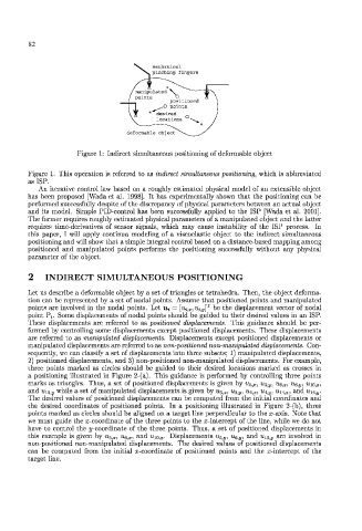
Figure 1: Indirect simultaneous positioning of deformable object
Figure 1. This operation is referred to as indirect simultaneous positioning, which is abbreviated
as ISP.
An iterative control law based on a roughly estimated physical model of an extensible object
has been proposed [Wada et al. 1998]. It has experimentally shown that the positioning can be
performed successfully despite of the discrepancy of physical parameters between an actual object
and its model. Simple PID-control has been successfully applied to the ISP [Wada et al. 2001],
The former requires roughly estimated physical parameters of a manipulated object and the latter
requires time-derivatives of sensor signals, which may cause instability of the ISP process. In
this paper, I will apply continua modeling of a viscoelastic object to the indirect simultaneous
positioning and will show that a simple integral control based on a distance-based mapping among
positioned and manipulated points performs the positioning successfully without any physical
parameter of the object.
2 INDIRECT SIMULTANEOUS POSITIONING
Let us describe a deformable object by a set of triangles or tetrahedra. Then, the object deforma-
tion can be represented by a set of nodal points. Assume that positioned points and manipulated
points are involved in the nodal points. Let u,; = [u,;^, u,;. ?/] T be the displacement vector of nodal
point P;. Some displacements of nodal points should be guided to their desired values in an ISP.
These displacements are referred to as positioned displacements. This guidance should be per-
formed by controlling some displacements except positioned displacements. These displacements
are referred to as manipulated displacements. Displacements except positioned displacements or
manipulated displacements are referred to as non-positioned non-manipulated displacements. Con-
sequently, we can classify a set of displacements into three subsets; 1) manipulated displacements,
2) positioned displacements, and 3) non-positioned non-manipulated displacements. For example,
three points marked as circles should be guided to their desired locations marked as crosses in
a positioning illustrated in Figure 2-(a). This guidance is performed by controlling three points
marks as triangles. Thus, a set of positioned displacements is given by u 5. x, u- a^. u 6_ x, u 6^, u iOx,
and 'iiio.y while a set of manipulated displacements is given by w.3,3, U;}, y, u i/x, u^ y, ii^ x, and Un, y.
The desired values of positioned displacements can be computed from the initial coordinates and
the desired coordinates of positioned points. In a positioning illustrated in Figure 2-(b), three
points marked as circles should be aligned on a target line perpendicular to the x-axis. Note that
we must guide the .'/.-coordinate of the three points to the .x-intcrcept of the line, while we do not
have to control the j/-coordinate of the three points. Thus, a set of positioned displacements in
this example is given by u^, x, u e^ x, and Uio, x- Displacements u 5ty, u$, y, and « 1() ,y are involved in
non-positioned non-manipulated displacements. The desired values of positioned displacements
can be computed from the initial x-coordinate of positioned points and the x-intercept of the
target line.