
Page 101 - Mechatronics for Safety, Security and Dependability in a New Era
P. 101
Ch18-I044963.fm Page 85 Tuesday, August 1, 2006 2:59 PM
Tuesday, August
Page 85
1, 2006
Ch18-I044963.fm
2:59 PM
85 85
-3 - 2 - 1 0 1 -3 -2 - 1
(a) 0.00 s (b) 1.00 s (c) 2.00 s
(d) 3.00 s (e) 4.00 s (f) 5.00 s
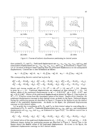
Figure 4: Process of indirect simultaneous positioning to desired points
three points P3, P,i, and P H . Positioned displacements are u-,.. T , u- h!J, ug, x, ue_ y, «io, 3-, and u\a. y and
manipulated displacements are u^, x, u$, y, 'Ui.. T , u^ y, an,,, and uii iV, as illustrated in Figure 2-(a).
Let us introduce a distance-based mapping from the positioned displacements to the manipulated
displacements. Control law is then formulated as follows:
u ?l = -K[ J o * (u 6 - u* 6) dt, Ui = -Ki /„* (u 5 - Ug) dt, u 14 = -Kj /„* (u 10 - u| 0 ) dt.
The corresponding discrete control law is given by
K
K
4 J 1 = "3,!, - 'l(4,y - «6,s,)- "ta 1 = «4,j, ~ *"/(«*», ~ «5,!/), «14^ = "14,9 ~ l(4o,y ~ «10,j,)-
Elastic and viscous moduli are A da = 7.0, A vis = 4.0, /i' :la = 5.0, and /i vis = 2.0. Density
is given by p = 0.2. Positioned displacements are measured at time interval T = 0.5. Let
T
T
desired values of the positioned displacements be u% = [-0.20,0.10] , Ug = [0.30. -0.10] , and
T
w* 0 — [0.10, 0.30] . Motion of the positioned displacements is plotted in Figure 3. Gain is given by
Ki — 1.7. Vibration conies from the viscoclastic nature of the object. Despite of the vibration, the
positioned displacements converge to their desired values, as shown in the figure. Deformed shapes
during the positioning process are described in Figure 4. Crosses in the figures denote the desired
values of the positioned displacements. As shown in the figure, the positioned displacements
converge to their desired values.
Let us guide the x-coordinates of P5, Pg, and P10 to their desired values by controlling the x-
^
coordinates of P3, P4, and P14. Positioned displacements are j . , 11^.,., and «io,.x- and manipulated
displacements are u$, x, ?/ 4ia:, and a^,, as illustrated in Figure 2-(b). The discrete control law is
then given by
Let desired values of the positioned displacements be u\ x — 0.20, u* ix = —0.20, and u\ Ox — —0.20.
Deformed shapes during the positioning process are described in Figure 5. Dotted lines in the
figures denote the desired values of the positioned displacements. As shown in the figure, the
positioned displacements converge to their desired values.