
Page 152 - Methods For Monitoring And Diagnosing The Efficiency Of Catalytic Converters A Patent - oriented Survey
P. 152
134 Methods for Monitoring and Diagnosing the Eficiency of Catalytic Converters
3) comparing a wave form of a signal output from the upstream airhe1 ratio sensor with a
wave form of a signal output from the downstream aidfuel ratio sensor, based on said first
to fourth signals while the engine is in a predetermined stable operating condition
4) determining from a result of this comparison whether or not the three-way catalyst is
deteriorated.
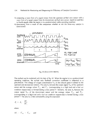
FC: Fuel Cut
Fig. 63 (from US5 158059)
The method can be explained with the help of fig. 63. When the engine is in a predetermined
operating condition, the aidfuel ratio feedback correction coefficient is subjected to a
perturbation. This change of oxygen concentration V02 in the exhaust gases is sensed by the
upstream and downstream sensors. The area A, between the output signal V02 of the upstream
sensor and the average values r,,, and FFc (corresponding to a high load and a fie1 cut
condition respectively) is formed during a time period T. Similarly, the area A2 between the
output signal V02 of the downstream sensor and the average values and cFc
(corresponding to a high load and a fuel cut condition respectively) is formed during a time
period T. The area A2 is then corrected by using the expression
where