
Page 261 - Methods For Monitoring And Diagnosing The Efficiency Of Catalytic Converters A Patent - oriented Survey
P. 261
Emitec Gesellschafi fiir Emissionstechnologie - Dr. Ing. H.c.F. Porsche AG 243
The temperature sensors can have the form of fig. 102 or can be mounted on a jacket surface
of the catalytic converter (fig. 103). This version is advantageous because it does not require
any alterations in the interior of the catalytic converter.
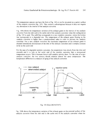
Fig. 104a shows the temperature variation of the exhaust gases in the interior of the catalytic
converter from the inlet end to the outlet end of the catalytic converter when the configuration
of fig. 102 is used. The solid line corresponds to a new catalytic converter, where the broken
line corresponds to a degraded one. The temperature of the exhaust gases flowing in the
catalytic converter is higher than a predetermined value in order to activate the catalytic
converter. For a new catalytic converter the maximum temperature of the exhaust gases is
attained immediately downstream of the inlet of the catalytic converter and it remains constant
as far as the outlet end.
For the case of a degraded catalytic converter, the temperature rises slowly from the inlet end
onwards and it is only at the outlet end of the catalytic converter that a pronounced
temperature occurs. This is because there is still catalytic activity there. For the case of a new
catalytic converter, the two sensors should measure almost the same temperature. The
temperature difference is a measure of aging of the catalytic converter.
- :new catalyst
T reaction zone
--- :deteriorated catalyst
I I I
/’ 1
/
// ’
/’ I I
rc/ I
1 measuring f 1 I 1 measuring I I
I
I
path
pa!h
I
,\ I fi. 1 7-
inlet outlet inlet outlet
Fig. 104 (from DE4027207)
Fig. 104b shows the temperature variation of the exhaust gases on the external surface of the
catalytic converter from the inlet end to the outlet end of the catalytic converter when the