
Page 273 - Methods For Monitoring And Diagnosing The Efficiency Of Catalytic Converters A Patent - oriented Survey
P. 273
Nissan Motor Co. 255
Alternatively a second temperature sensor can be installed downstream of the first sensor, with
respect to flow of the exhaust gas, to produce a second catalytic converter temperature
indicative signal (fig. 1 IO). A difference of the first and second catalytic converter temperature
indicative signals is derived and compared with the reference value generated at step 3. This
comparison gives useful information about the condition of the catalytic converter.
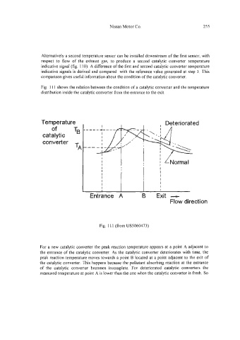
Fig. 11 I shows the relation between the condition of a catalytic converter and the temperature
distribution inside the catalytic converter from the entrance to the exit.
1 I I
I I
I I
I I
I I
I
I I
I I
Fig. 11 1 (from USS060473)
For a new catalytic converter the peak reaction temperature appears at a point A adjacent to
the entrance of the catalytic converter. As the catalytic converter deteriorates with time, the
peak reaction temperature moves towards a point B located at a point adjacent to the exit of
the catalytic converter. This happens because the pollutant absorbing reaction at the entrance
of the catalytic converter becomes incomplete. For deteriorated catalytic converters the
measured temperature at point A is lower than the one when the catalytic converter is fresh. So