
Page 79 - Methods For Monitoring And Diagnosing The Efficiency Of Catalytic Converters A Patent - oriented Survey
P. 79
Daimler-Benz AG 61
In GB2178857 (1987) another workshop test method is applied. At idling or fast idling
conditions, a forced switch of the engine airhe1 ratio fiom rich to lean and the opposite takes
place. By introducing a delay element (RC element or a low pass filter) in the control circuit of
the 1. probe located upstream of the catalytic converter, the switch is retarded by 10 to 5000
msec (preferably 50 to 200 msec). The amount of measured remaining combustible
constituents in the exhaust gases after the catalytic converter is a measure of its condition.
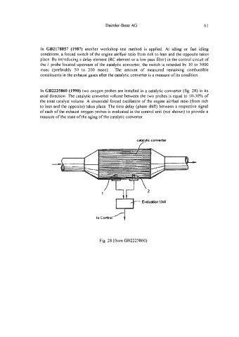
In GB2225860 (1990) two oxygen probes are installed in a catalytic converter (fig. 28) in its
axial direction. The catalytic converter volume between the two probes is equal to 10-30% of
the total catalyst volume. A sinusoidal forced oscillation of the engine aidfuel ratio (fiom rich
to lean and the opposite) takes place. The time delay (phase shift) between a respective signal
of each of the exhaust oxygen probes is evaluated in the control unit (not shown) to provide a
measure of the state of the aging of the catalytic converter.
catalytic converter
Evaluation Unit
Fig. 28 (from GB2225860)