
Page 98 - Methods For Monitoring And Diagnosing The Efficiency Of Catalytic Converters A Patent - oriented Survey
P. 98
80 Methods for Monitoring and Diagnosing the Efficiency of Catalytic Converters
Engines with multiple cylinder groups
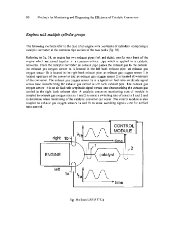
The following methods refer to the case of an engine with two banks of cylinders comprising a
catalytic converter at the common pipe section of the two banks (fig. 38).
Referring to fig. 38, an engine has two exhaust pipes (left and right), one for each bank of the
engine which are joined together in a common exhaust pipe which is applied to a catalytic
converter. From the catalytic converter an exhaust pipe passes the exhaust gas to the outside.
An exhaust gas oxygen sensor la is located in the left bank exhaust pipe, an exhaust gas
oxygen sensor Ib is located in the right bank exhaust pipe, an exhaust gas oxygen sensor 1 is
located upstream of the converter and an exhaust gas oxygen sensor 2 is located downstream
of the converter. The exhaust gas oxygen sensor la is a typical air fuel ratio amplitude signal
versus time characterizing the exhaust gas carried in let? bank exhaust pipe. The exhaust gas
oxygen sensor 1 b is an air fuel ratio amplitude signal versus time characterizing the exhaust gas
carried in the right bank exhaust pipe. A catalytic converter monitoring control module is
coupled to exhaust gas oxygen sensors 1 and 2 to sense a switching rate of sensors 1 and 2 and
to determine when monitoring of the catalytic converter can occur. The control module is also
coupled to exhaust gas oxygen sensors la and Ib to sense switching signals used for aidfuel
ratio control.
Fig. 38 (from US5357753)