
Page 99 - Methods For Monitoring And Diagnosing The Efficiency Of Catalytic Converters A Patent - oriented Survey
P. 99
Ford Motor Co. - Ford France SA - Ford Werke AG - Ford Motor Co. Ltd. 81
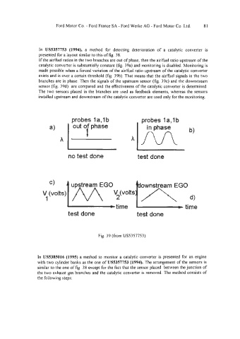
In US5357753 (1994), a method for detecting deterioration of a catalytic converter is
presented for a layout similar to this of fig. 38.
If the airlfuel ratios in the two branches are out of phase, then the aidfuel ratio upstream of the
catalytic converter is substantially constant (fig. 39a) and monitoring is disabled. Monitoring is
made possible when a forced variation of the aidtiel ratio upstream of the catalytic converter
exists and is over a certain threshold (fig. 39b). That means that the airhe1 signals in the two
branches are in phase. Then the signals of the upstream sensor (fig. 39c) and the downstream
sensor (fig. 39d) are compared and the effectiveness of the catalytic converter is determined.
The two sensors placed in the branches are used as feedback elements, whereas the sensors
installed upstream and downstream of the catalytic converter are used only for the monitoring.
probes 1 a,l b probes 1 a,l b
out of phase
I
A
no test done test done
ownstream EGO
a
time time
test done test done
Fig. 39 (from US5357753)
In US5385016 (1995) a method to monitor a catalytic converter is presented for an engine
with two cylinder banks as the one of US5357753 (1994). The arrangement of the sensors is
similar to the one of fig. 38 except for the fact that the sensor placed between the junction of
the two exhaust gas branches and the catalytic converter is removed. The method consists of
the following steps: