
Page 104 -
P. 104
94 3 Optical Tweezers
y
(ab)
Focus point o 0
-1 S 1 Z
Fig. 3.14. Geometry for calculating exact axial trapping efficiency for microsphere
considering beam waist
0.5
0.45
0.4
Trapping efficiency 0.25 Beam waist Ray optics
0.35
0.3
s
0.2
0.15
20 mm
0.1 Diameter
10
0.05 5
2
0 1
0 0.2 0.4 0.6 0.8 1
Normalized distance between particle center and focus point
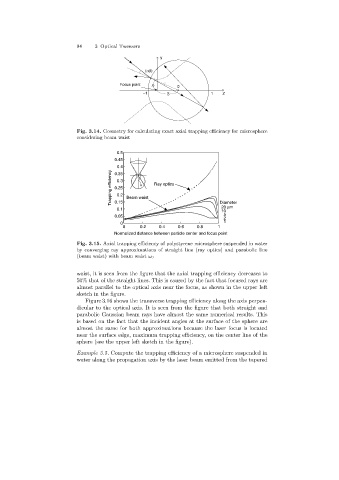
Fig. 3.15. Axial trapping efficiency of polystyrene microsphere suspended in water
by converging ray approximations of straight line (ray optics)and parabolic line
(beam waist)with beam waist ω 0
waist, it is seen from the figure that the axial trapping efficiency decreases to
50% that of the straight lines. This is caused by the fact that focused rays are
almost parallel to the optical axis near the focus, as shown in the upper left
sketch in the figure.
Figure 3.16 shows the transverse trappingefficiency alongthe axis perpen-
dicular to the optical axis. It is seen from the figure that both straight and
parabolic Gaussian beam rays have almost the same numerical results. This
is based on the fact that the incident angles at the surface of the sphere are
almost the same for both approximations because the laser focus is located
near the surface edge, maximum trapping efficiency, on the center line of the
sphere (see the upper left sketch in the figure).
Example 3.5. Compute the trappingefficiency of a microsphere suspended in
water alongthe propagation axis by the laser beam emitted from the tapered