
Page 109 -
P. 109
3.2 Theoretical Analysis 99
the incident angle θ 1 on the arbitrary intersection (x, y, z)ofthesurfaceofa
sphere, whose center is located at (0,B,A). The y-coordinate is expressed as
2
2
y (x,z) = B + r − x − (z − A) 2 (3.12)
The beam profiles for the x-and y-directions are given as
2 2
z z
ω y = tω 0 1+ , ω x = uω 0 1+ , (3.13)
Z 0 Z 0
where ω 0 is the radius at the beam waist, Z 0 is the depth of focus, and
t(0 ≤ t ≤ 1) and u(0 ≤ u ≤ 1) are variable parameters.
Next, the incident angle θ 1 of a ray enteringthe sphere at the inter-
section point (x, y, z) is defined as the angle between the tangential vector
a = ω ,ω , 1 of the ray and the vector b = x, B − y (x,z) ,A − z pointing
y
x
from the intersection (x, y, z) to the center (0,B,A) of the sphere
ab
θ 1 = arccos . (3.14)
|a|·|b|
As a result, the trappingefficiencies Q s(x,z) and Q g(x,z) owingto a ray
hits the intersection (x, y, z) can be obtained using(3.5) and (3.6). The entire
trappingefficiency due to the entire surface of the microsphere is given later.
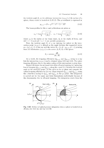
Figure 3.20 shows the sectional view of the off-axial trapping (a), indicating
how to integrate Q s(x,z) and Q g(x,z) alongthe z-axis (b). Calculate the incident
angle at the arbitrary point z in the circle in the yz plane and compute the
optical trappingefficiency for the ray. Then integrate Q s(x,z) and Q g(x,z) along
z z
the z-direction leadingto Q s (x) and Q g (x) in the yz plane. The integration
is carried out for the upper and lower hemispheres individually because of
the dissymmetry due to off-axial trapping. The integration starts from the
(a) (b)
Beam profile Beam profile
Y X x(u max )
z upper (t )
(x) max
(t )
z (x) min dz dx
A-r z x=0 z
z lower (t max )
(x)
Fig. 3.20. Method of optical pressure integration when a sphere is located at an
off-axis, side view (a), and top view (b)