
Page 114 -
P. 114
104 3 Optical Tweezers
Monitor
Cover glass Liquid Slide glass CCD YAG laser
Dichroic mirror
l/4 plate
Spacer
Objective lens
Upper objective
ND filter
Enlarged view Stage
Lower objective
Beam expander
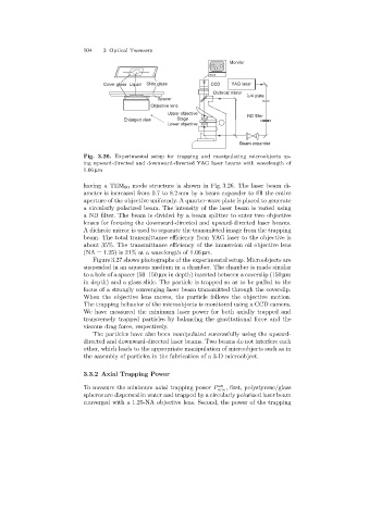
Fig. 3.26. Experimental setup for trapping and manipulating microobjects us-
ing upward-directed and downward-directed YAG laser beams with wavelength of
1.06 µm
havinga TEM 00 mode structure is shown in Fig. 3.26. The laser beam di-
ameter is increased from 0.7 to 8.2 mm by a beam expander to fill the entire
aperture of the objective uniformly. A quarter-wave plate is placed to generate
a circularly polarized beam. The intensity of the laser beam is varied using
a ND filter. The beam is divided by a beam splitter to enter two objective
lenses for focusingthe downward-directed and upward-directed laser beams.
A dichroic mirror is used to separate the transmitted image from the trapping
beam. The total transmittance efficiency from YAG laser to the objective is
about 35%. The transmittance efficiency of the immersion oil objective lens
(NA = 1.25) is 21% at a wavelength of 1.06 µm.
Figure 3.27 shows photographs of the experimental setup. Microobjects are
suspended in an aqueous medium in a chamber. The chamber is made similar
to a hole of a spacer (50–150 µm in depth) inserted between a coverslip (150 µm
in depth) and a glass slide. The particle is trapped so as to be pulled to the
focus of a strongly converging laser beam transmitted through the coverslip.
When the objective lens moves, the particle follows the objective motion.
The trappingbehavior of the microobjects is monitored usinga CCD camera.
We have measured the minimum laser power for both axially trapped and
transversely trapped particles by balancingthe gravitational force and the
viscous dragforce, respectively.
The particles have also been manipulated successfully usingthe upward-
directed and downward-directed laser beams. Two beams do not interfere each
other, which leads to the appropriate manipulation of microobjects such as in
the assembly of particles in the fabrication of a 3-D microobject.
3.3.2 Axial Trapping Power
To measure the minimum axial trappingpower P ax , first, polystyrene/glass
min
spheres are dispersed in water and trapped by a circularly polarized laser beam
converged with a 1.25-NA objective lens. Second, the power of the trapping