
Page 175 -
P. 175
4.6 Mixer Application for µ-TAS 165
(a) (b)
500rpm
Flow velocity: 67 mms -1 Wing top velocity: 530 mms -1
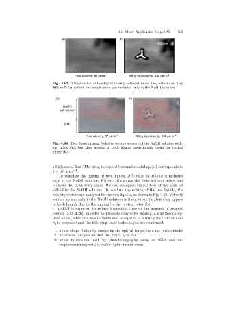
Fig. 4.67. Visualization of two-liquid mixing: without mixer (a), with mixer (b);
20% milk fat colloid for visualization was included only in the NaOH solution
(a) (b)
NaOH
with colloid
BTB
Flow velocity: 67 mms -1 Wing top velocity: 530 mms -1
Fig. 4.68. Two-liquid mixing. Velocity vectors appear only in NaOH solution with-
out mixer (a), but they appear in both liquids upon mixing using the optical
mixer (b).
a high-speed flow. The wing top speed (circumferential speed) corresponds to
3
1 × 10 µms −1 .
To visualize the mixingof two liquids, 20% milk fat colloid is included
only in the NaOH solution. Figure 4.67a shows the flows without mixer and
b shows the flows with mixer. We can recognize stirred flow of the milk fat
colloid in the NaOH solution. To confirm the mixingof the two liquids, the
velocity vectors are analyzed for the two liquids, as shown in Fig. 4.68. Velocity
vectors appear only in the NaOH solution without mixer (a), but they appear
in both liquids due to the mixingby the optical rotor (b).
µ-TAS is expected to reduce inspection time or the amount of reagent
needed [4.25,4.26]. In order to promote convective mixing, a shuttlecock op-
tical mixer, which rotates in fluids and is capable of stirringthe fluid around
it, is proposed and the followingbasic technologies are confirmed:
1. mixer shape design by analyzing the optical torque by a ray optics model
2. microflow analysis around the mixer by CFD
3. mixer fabrication both by photolithography using an SU-8 and mi-
crophotoformingwith a visible light-curable resin